Toyota Corolla (E120) 2002–2008 Repair Manual / Diagnostics / Combination meter / Malfunction in speedometer
Toyota Corolla (E120): Malfunction in speedometer
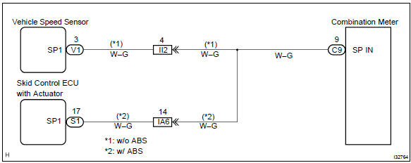
Wiring diagram
Inspection procedure
1 Check combination meter assy
- Remove the combination meter assy with connector still connected.
- check voltage.
- Jack up either of the front wheels.
- Shift the shift lever to neutral.
- Turn the ignition switch to on.
- Measure the voltage between terminals c9–9 of combination meter assy and body ground when front wheel is turning slowly.
Standard voltage: voltage is generated intermittently.
Result:


Check and replace combination meter assy
2 Check obd ii scan tool or hand–held tester
- Check output value of skid control ecu.
- Connect the hand–held tester to dlc3.
- Turn the ignition switch to on and push the hand–held tester main switch on.
- Select the data list mode on the hand–held tester.
- Check that there is no difference between the speed value output
from the speed sensor displayed
by the hand–held tester and the speed value displayed by the speedometer
when driving
the vehicle.
Ok: there is almost no difference from the displayed speed value.


Repair or replace harness or connector
3 Inspect speedometer sensor
- Check voltage.
- Shift the shift lever to neutral.
- Jack up either of the front wheel.
- Turn the ignition switch to on.
- Measure voltage between terminals 3 and 2 of speed sensor when the front wheel is turning slowly.
Standard voltage: voltage is generated intermittently.

Repair or replace harness or connector


Other materials:
Rear door belt moulding assy lh
Replacement
Hint:
the installation procedures are the removal procedures in reverse
order.
Use the same procedures for the rh side and lh side.
1. Remove rear armrest assy lh
2. Remove power window regulator switch assy rear (w/ power window)
3. Remove rear door window regulator han ...
Air conditioning controls
■ Adjusting the temperature setting
To adjust the temperature setting, turn
clockwise to increase the temperature
and turn counterclockwise to decrease
the temperature.
■ Fan speed setting
Press “>” on to increase the fan
speed.
Press “<” on to decrease the ...
Front passenger occupant classification
system
Your vehicle is equipped with a front passenger occupant
classification system. This system detects the conditions of
the front passenger seat and activates or deactivates the front
passenger airbag and seat cushion airbag in the front passenger
side.
System components
SRS warning light
Front pa ...