Toyota Corolla (E120): Inspection procedure
1 Check connector
- Disconnect the negative (–) terminal cable from the battery, and wait at least for 90 seconds.
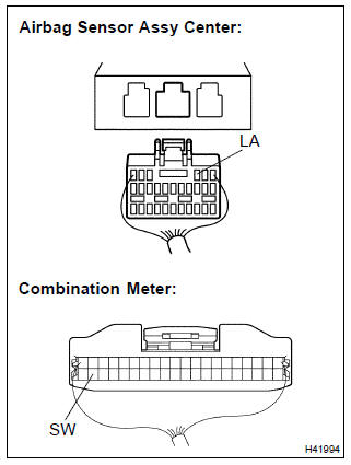
- check the connection of the combination meter connector and the
airbag sensor assy center connectors.
Ok: the connectors are connected.


2 Check combination meter assy
- Disconnect the connector from the combination meter.
- connect the negative (–) terminal cable to the battery, and wait at least for 2 seconds.
- Turn the ignition switch to on, and wait at least for 6 seconds.
- measure the voltage between sw and body ground.
Ok: voltage: above 8 v


3 Check instrument panel wire(airbag sensor assy center–combination meter assy)
- Turn the ignition switch to lock.
- disconnect the negative (–) terminal cable from the battery, and wait at least for 90 seconds.
- disconnect the connector from the airbag sensor assy center.
- measure the resistance between la and body ground.
Ok: resistance: 1mΩ or higher

Replace air bag sensor assy center
4 Check instrument panel wire(airbag sensor assy center–combination meter assy)
- For the connector (on the airbag sensor assy center side)
between the combination meter and the airbag sensor
assy center, measure the resistance between sw and
la.
Ok: resistance: below 1 Ω

Replace air bag sensor assy center

 Srs warning light circuit malfunction (does not light
up, when ignition switch is turned to on)
Srs warning light circuit malfunction (does not light
up, when ignition switch is turned to on)
Other materials:
Using the radio (Multimedia system)
Radio operation
Select “AM” or “FM” on the audio source selection screen to begin listening
to the radio.
Audio control screen
Pressing the “AUDIO” button displays the audio control screen from any screens
of the selected source.
1 Audio source selection screen appears
2 Preset ...
Front no.1 Speaker assy
Replacement
Hhint: components:
1. Remove front armrest assy lh
2. Remove power window regulator master switch assy (w/ power window)
3. Remove front armrest base panel upper lh (w/o power window)
4. Remove front door window regulator handle assy (w/o power window)
5. Remove front door lowe ...
Audio unit
1 Bluetooth® connection status
If “BT” is not displayed, the Bluetooth® audio/phone cannot be used.
2 Display
A message, name, number, etc. is displayed.
Lower-case characters and special characters cannot be displayed.
3 Displays the set up menu
4 Selects items such as menu and number
...