
Toyota Corolla (E120) 2002–2008 Repair Manual / Diagnostics / Combination meter / Malfunction in tachometer
Toyota Corolla (E120): Malfunction in tachometer
Wiring diagram
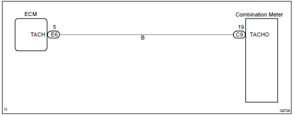
Inspection procedure

- Check output value of ecm.
- Connect the hand–held tester to dlc3.
- Turn the ignition switch to on and push the hand–held tester main switch on.
- Select the data list mode on the hand–held tester.


2 Inspect combination meter assy

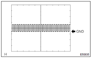
(Reference) inspection using oscilloscope
- check the input signal waveform.
- Remove the combination meter assy with connectors still connected.
- Connect the oscilloscope to the terminals c9–19 of combination meter assy and body ground.
- Start engine.
- Check the signal waveform.



3 Check harness and connector(between ecm and combination meter assy)
- Remove the combination meter.
- check the continuity between terminals 5 (tach) of ecm and c9–19 of combination meter connector.
Standard: there is continuity.


Check and replace ecm


Other materials:
Registering a Bluetooth® phone for the first time
To use the hands-free system, it is necessary to register a Bluetooth® phone
with the system.
Once the phone has been registered, it is possible to use the hands-free system.
For details about registering a Bluetooth® device
1 Turn the Bluetooth® connection setting of your cellular phone on. ...
Mass or volume air flow circuit
Dtc p0100 mass or volume air flow circuit
Dtc p0102 mass or volume air flow circuit
low input
Dtc p0103 mass or volume air flow circuit
high input
Circuit description
The maf (mass air flow) sensor measures the amount of air flowing through the
throttle valve. The ecm
uses this information ...
Listing the registered cellular phones
Select “List Phone” using .
The list of registered cellular phones will be displayed.
● Connecting the registered cellular phone to the audio system
1 Select the name of the cellular phone to be connected using
.
2 Select “Select” using .
● Deleting a registered cell ...