Toyota Corolla (E120): Overhaul
1. Remove manual transaxle assy
2. Remove clutch release fork sub–assy
- Remove the clutch release fork with clutch release bearing from the transaxle assy.
3. Remove clutch release bearing assy
- remove the clutch release bearing assy from the clutch release fork.
4. Remove release fork support
- remove the release fork support from the transaxle assy.
5. Remove release bearing hub clip
6. Remove clutch release fork boot
7. Remove clutch cover assy
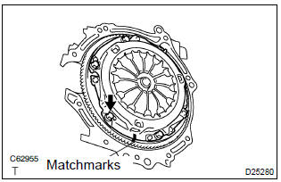
- Align the matchmarks on the clutch cover assy with the one on the flywheel sub–assy.
- loosen each set bolt one turn at a time until spring tension is released.
- remove the 6 bolts, and pull off the clutch cover assy.
Notice
: do not drop the clutch disc assy.
8. Remove clutch disc assy
Notice
: keep the lining part of the clutch disc assy, the pressure plate and surface of the flywheel sub–assy away from oil and foreign attachment.
9. Inspect clutch disc assy
- Using vernier calipers, measure the rivet head depth.
Maximum rivet depth: 0.3 Mm (0.012 In.)
If necessary, replace the clutch disc assy.
- install the clutch disc assy to the transaxle assy.
Notice
: take care not to insert the clutch disc assy in the wrong direction.
- Using a dial indicator, check the clutch disc assy runout.
Minimum runout: 0.8 Mm (0.031 In.)
If necessary, replace the clutch disc assy.
10. Inspect clutch cover assy
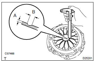
- Using vernier calipers, inspect the diaphragm spring for
depth and width of wear.
Maximum:
a (depth): 0.5 Mm (0.020 In.) B (width): 6.0 Mm (0.236 In.)
If necessary, replace clutch cover assy.
11. Inspect flywheel sub–assy
- Using a dial indicator, inspect the flywheel sub–assy runout.
Maximum runout: 0.1 Mm (0.004 In.)
If necessary, replace the flywheel sub–assy.
12. Inspect clutch release bearing assy
- Turn the release bearing by hand while applying force in the axial direction.
Hint
: the bearing is permanently lubricated and requires no cleaning or lubrication. If necessary, replace the release bearing assy.
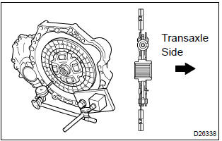
13. Install clutch disc assy
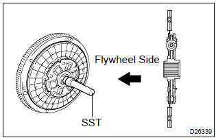
- Insert sst in the clutch disc assy, then insert them in the
flywheel sub–assy.
Sst 09301–00210
Notice
: take care not to insert clutch disc assy in the wrong direction.
14. Install clutch cover assy
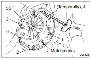
- Align the matchmarks on the clutch cover assy and flywheel sub–assy.
- following the procedures shown in the illustration, tighten
the 6 bolts, in the order starting the bolt locating near the
knock pin on the top.
Torque: 19.1 Nvm (195 Kgf·cm, 14 ft·lbf)
H
int
:
- following the order in the illustration, tighten the bolts at a time evenly.
- Move sst up and down, right and left lightly, after checking that the disc is in the center, tighten the bolts.
15. Inspect and adjust clutch cover assy
- Using a dial indicator with roller instrument, check the diaphragm
spring tip alignment.
Maximum non–alignment: 0.5 Mm (0.020 In.)
If alignment is not as specified, using sst, adjust the diaphragm spring tip alignment.
Sst 09333–00013
16. Install release fork support
- install the release fork support to the transaxle assy.
Torque: 36.8 Nvm (375 Kgf·cm, 27 ft·lbf)
17. Install release bearing hub clip
18. Install clutch release fork sub–assy
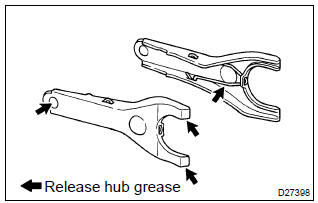
- Apply release hub grease to the release fork and release
bearing assy contact, release fork and push rod contact
and release fork pivot points.
Sealant:
part no. 08887–01806, Release hub grease or equivalent - install the release fork to the release bearing assy.
19. Install clutch release bearing assy
- apply the clutch spline grease to the input shaft spline.
Sealant: part no. 08887–01706, Clutch spline grease or equivalent
- install the bearing to the release fork, and then install them to the transaxle assy.
Notice
: after the installation, move the folk forward and backward to check that the release bearing slides smoothly.
20. Install clutch release fork boot
21. Install manual transaxle assy


Other materials:
Seat belt warning lamp for front passenger’s seat
does not flash
Wiring diagram
Inspection procedure
1 Inspect combination meter assy
Ground terminal c9–11 on the combination meter side.
check that the warning lightlights up.
Ok: warning light lights up.
2 Inspect passenger seat belt warning lamp assy
Ground terminal c9– ...
Rear seats
The seatbacks of the rear seats can be folded down.
The seatbacks of the rear seats can be folded down.
1 Stow the rear outside seat belt buckles and stow the rear center seat belt
buckle as shown.
2 Pull the seatback lock release knob and fold the seatback down.
CAUTION
■When foldi ...
Power steering
Preparation
Sst
Recomended tools
Equipment
Lubricant
Ssm
...