Toyota Corolla (E120): Overhaul
1. Remove manual transmission filler plug
- Remove the manual transmission filler plug and gasket from the manual transmission case.
2. Remove drain (mtm) plug sub–assy
- Remove the drain (mtm) plug sub–assy and gasket from the manual transmission case.
3. Remove speedometer sensor (w/o abs)
- remove the bolt and speedometer sensor from the transaxle case.
- remove the o–ring from the speedometer sensor.
4. Remove speedometer driven (mtm) gear sub–assy (w/o abs)
- remove the clip and speedometer driven (mtm) gear sub–assy from the speedometer sensor.
5. Remove speedometer driven hole cover sub–assy (w/ abs)
- remove the bolt and speedometer driven hole cover sub–assy from the transaxle case.
- remove the o–ring from the speedometer driven hole cover.
6. Remove clutch release fork sub–assy
- Remove the clutch release fork sub–assy with clutch release bearing assy from the transaxle case.
7. Remove clutch release bearing assy
- Remove the clutch release bearing clip and clutch release bearing assy from the clutch release fork sub–assy.
8. Remove release fork support
- Remove the clutch release fork support from the transaxle case.
9. Remove clutch release fork boot
- Remove the clutch release fork boot from the transaxle case.
10. Remove back up lamp switch assy
- Remove the back up lamp switch assy and gasket from the manual transmission case.
11. Remove floor shift control lever housing support bracket
- Remove the 3 bolts and floor shift control lever housing support bracket from the transaxle case.
12. Remove selecting bell crank assy
- Remove the 2 bolts and selecting bellcrank assy from the manual transmission case.
- remove the control shift lever bush.
13. Fix manual transaxle assy
- Using 2 wooden blocks, fix the manual transaxle assy.
14. Remove lock ball assy no.1
- Remove the lock ball assy no.1 From the manual transmission case.
15. Remove shift & select lever shaft assy
- Remove the 4 bolts, shift & select lever shaft assy and gasket from the manual transmission case.
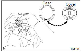
16. Remove manual transmission case cover sub–assy
- Remove the 9 bolts.
- Using a plastic hammer, carefully tap the projection of the manual transmission case cover sub–assy to remove it from the manual transmission case.
Notice
: do not damage the manual transmission case.
17. Remove manual transmission output shaft rear set nut
- Using a chisel and a hammer, loosen the staked part of the manual transmission output shaft rear set nut.
- Engage the gear to the double meshing.
- remove the manual transmission output shaft rear set nut.
- disengage the double mashing of the gear.
18. Remove gear shift fork no.3
- Remove the gear shift fork lock bolt from the gear shift fork no.3.
- Remove the transmission hub sleeve no.3 With gear shift fork no.3 From the transmission clutch hub no.3.
19. Inspect 5th gear thrust clearance
- Using a dial indicator, measure the 5th gear thrust clearance.
5Th gear thrust clearance:

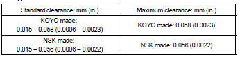
20. Inspect 5th gear radial clearance
- Using a dial indicator, measure the 5th gear radial clearance.
5Th gear radial clearance: mm (in.)
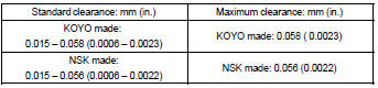
If the clearance exceeds the maximum, replace the gear, needle roller bearing or shaft.
21. Remove transmission clutch hub no.3
- Using 2 screwdrivers and a hammer, tap out the snap ring.
Hint
: using a waste to prevent the snap ring from being scattered.
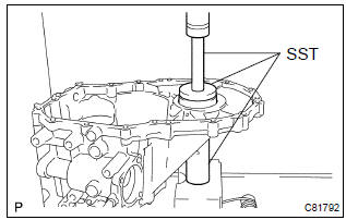
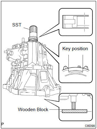
- Using sst, remove the transmission clutch hub no.3, 5Th
gear and synchronizer ring no.3 From the input shaft.
Sst 09950–40011 (09951–04020, 09952–04010, 09953–04030, 09954–04010, 09955–04071, 09957–04010), 09950–60010 (09951–00200)
- Remove the 3 synchromesh shifting keys and 2 synchromesh shifting key springs from the transmission clutch hub no.3.
22. Remove 5th gear needle roller bearing
- Remove the 5th gear needle roller bearing and 5th gear bearing spacer from the input shaft.
23. Remove 5th driven gear
- Using sst, remove the 5th driven gear from the output
shaft.
Sst 09950–30012 (09951–03010, 09953–03010, 09954–03010, 09955–03011, 09957–04010), 09950–60010 (09951–00190)
24. Remove bearing retainer rear (mtm)
- Remove the 5 bolts and bearing retainer rear (mtm) from the manual transmission case.
25. Remove output shaft rear bearing hole snap ring
- Using a snap ring expander, remove the output shaft rear bearing hole snap ring from the output shaft.
26. Remove input shaft rear bearing hole snapring
- Using a snap ring expander, remove the input shaft rear bearing hole snap ring from the input shaft.
27. Remove reverse idler gear shaft bolt
- Remove the reverse idler gear shaft bolt and gasket from the manual transmission case.
28. Remove shift fork shaft shaft snap ring
- Using 2 screwdrivers and a hammer, tap out the snap ring from the gear shift fork shaft no.2.
Hint
: using a waste to prevent the snap ring from being scattered.
29. Remove shift detent ball
- Using a hexagon wrench, remove the 2 shift detent ball plugs from the manual transmission case.
- Using a magnetic finger, remove the 2 seats, 2 springs and 2 shift detent balls from the manual transmission case.
- Using a hexagon wrench, remove the shift detent ball plug from the transaxle case.
- Using a magnetic finger, remove the seat, spring and shift detent ball from the transaxle case.
30. Remove lock ball assy no.1
- Using a hexagon wench, remove the lock ball assy no.1 From the manual transmission case.
31. Remove manual transmission case
- Remove the 3 bolts from the transaxle case side
- Remove the 13 bolts from the manual transmission case side.
- Using a brass bar and a hammer, carefully tap the projection of the manual transmission case to remove it from the transaxle case.
Notice
: do not damage the manual transmission case and transaxle case.
32. Remove reverse idler gear sub–assy
- Remove the reverse idler gear sub–assy, thrust washer and reverse idler gear shaft from the transaxle case.
33. Remove reverse shift arm bracket assy
- Remove the 2 bolts and reverse shift arm bracket assy from the transaxle case.
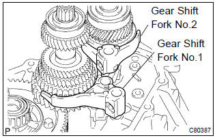
34. Remove gear shift fork shaft no.2

- Remove the 2 bolts from the gear shift fork no. 2 And gear shift head no.1.
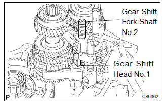
- Remove the gear shift fork shaft no.2 And gear shift head no.1 From the transaxle case.
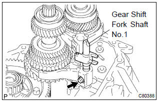
35. Remove gear shift fork shaft sub–assy no.1
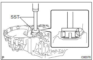
- Using 2 screwdrivers and a hammer, tap out the snap rings.
Hint
: using a waste to prevent the snap ring from being scattered.
- Remove the gear shift fork lock bolt and gear shift fork shaft sub–assy no.1 From the gear shift fork no.1.
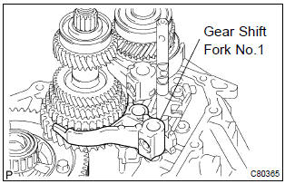
- Remove the gear shift fork no.1.
36. Remove gear shift fork shaft no.3
- Using 2 screwdrivers and a hammer, tap out the snap ring from the gear shift fork shaft no.3.
Hint
: using a waste to prevent the snap ring from being scattered.
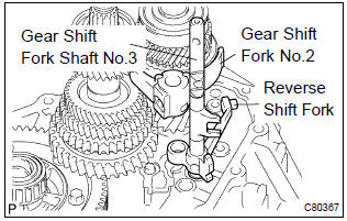
- Remove the shift fork shaft no.3 With reverse shift fork and gear shift fork no.2 From the transaxle case.
- Using a magnetic finger, remove the 2 balls from the reverse shift fork.
- Using 2 screwdrivers and a hammer, tap out the snap
ring.
Hint
: using a waste to prevent the snap ring from being scattered.
- remove the reverse shift fork from the gear shift fork shaft no.3.
37. Remove input shaft assy
- Remove the input and output shaft assy from the transaxle case.
38. Remove differential case assy
- Remove the differential case assy from the transaxle case.
39. Remove manual transaxle case receiver
- Remove the bolt and manual transaxle case receiver from the transaxle case.
40. Remove reverse restrict pin assy
- Using a hexagon wrench, remove the reverse restrict pin plug from the manual transmission case.
- Using a pin punch (f 5 mm) and a hammer, drive out the slotted spring pin and remove the reverse restrict pin assy from the manual transmission case.
41. Remove oil receiver pipe no.1 (Mtm)
- Remove the bolt and oil receiver pipe no.1 (Mtm) from the manual transmission case.
Notice
: be careful not to damage the oil receiver pipe no.1 (Mtm).
42. Remove oil receiver pipe no.2 (Mtm)
- Remove the bolt and oil receiver pipe no.2 (Mtm) from the manual transmission case.
Notice
: be careful not to damage the oil receiver pipe no.2 (Mtm).
43. Remove bearing lock plate
- Remove the bolt and bearing lock plate from the transaxle case.
44. Remove transmission magnet
- Remove the transmission magnet from the transaxle case.
45. Remove input shaft front bearing
- Using sst, remove the input shaft front bearing from the
transaxle case.
Sst 09612–65014 (09612–01050, 09612–01060)
46. Remove front transaxle case oil seal
- Using a screwdriver, remove the front transaxle case oil seal from the transaxle case.
47. Remove output shaft front bearing
- Using sst, remove the output shaft front bearing from the
transaxle case.
Sst 09308–00010
48. Remove output shaft (mtm) cover
- Remove the output shaft (mtm) cover from the transaxle case.
49. Remove fr differential case front tapered roller bearing

- Using sst, remove the fr differential case front tapered
roller bearing (outer race) and shim from the transaxle
case.
Sst 09612–65014 (09612–01040, 09612–01050)
- Using sst, remove fr differential case front tapered roller
bearing (inner race) from the front differential case.
Sst 09950–00020, 09950–00030, 09950–40011 (09957–04010), 09950–60010 (09951–00360)
Тotice
: be careful not to damage bearing.
50. Remove transaxle case oil seal
- Using sst and a hammer, drive out the transaxle case oil
seal from the transaxle case.
Sst 09950–60010 (09951–00530), 09950–70010 (09951–07150)
51. Remove fr differential case rear tapered roller bearing
- Using sst, remove the fr differential case rear tapered
roller bearing (outer race) and shim from the manual
transmission case.
Sst 09612–65014 (09612–01040, 09612–01050)
- Using sst and a hammer, remove the fr differential
case rear tapered roller bearing (inner race) from the front
differential case.
Sst 09950–40011 (09951–04010, 09952–04010, 09953–04020, 09954–04010, 09955–04061, 09957–04010, 09958–04011), 09950–60010 (09951–00360)
Т
otice
: be careful not to damage bearing.
52. Remove transmission case oil seal
- Using sst and a hammer, remove the transmission case
oil seal from the manual transmission case.
Sst 09950–60010 (09951–00600), 09950–70010 (09951–07100)
53. Inspect synchronizer ring no.3
- Check for wear or damage.
- check the braking effect of the synchronizer ring. Turn the
synchronizer ring in one direction while pushing it to the
gear cone, check that the ring locks.
If the braking effect is insufficient, apply a small amount of the fine lapping compound between the synchronizer ring and gear cone. Lightly rub the synchronizer ring and gear cone together.
Notice
: ensure the file lapping compound is completely washed off after rubbing.
- check again the breaking effect of the synchronizer ring.
- Using a feeler gauge, measure the clearance between
the synchronizer ring back and gear spline end.
Minimum clearance: 0.75 Mm (0.0295 In.) If the clearance is less than minimum, replace the synchronizer ring and gear cone by applying a small amount of the fine lapping compound on gear cone.
Notice
: ensure the fine lapping compound is completely washed off after rubbing.
54. Inspect transmission hub sleeve no.3
- Check the sliding condition between the transmission hub sleeve no. 3 And transmission clutch hub no.3.
- check that spline gear’s of the transmission hub sleeve no.3 Is not worn down.
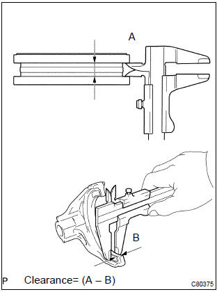
- Using a vernier calipers, inspect the transmission hub
sleeve no.3 And gear shift fork no.3 As shown in the illustration.
Standard clearance:
0.3 – 0.5 Mm (0.012 – 0.020 In.)
If the clearance is out of specification, replace the transmission hub sleeve no.3 And gear shift fork no.3.
55. Inspect 5th gear
- Using a caliper gauge, inspect 5th gear as shown in the
illustration.
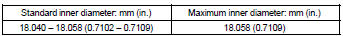
5Th gear inner diameter:

If the inner diameter exceeds the maximum, replace the 5th gear.
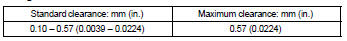
56. Inspect reverse idler gear sub–assy
- Using a caliper gauge, inspect the reverse idler gear sub– assy as shown in the illustration.
Reverse idler gear sub–assy inner diameter:
If the inner diameter exceeds the maximum, replace the reverse idler gear sub–assy.
- using a micrometer, inspect the reverse idler gear shaft as shown in the illustration.
Reverse idler gear shaft outer diameter:
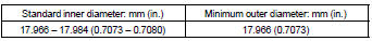
If the outer diameter is below the minimum, replace the reverse idler gear shaft.
57. Install output shaft (mtm) cover
- Coat the output shaft (mtm) cover with mp grease, install it to the transaxle case.
Notice
: install the output shaft (mtm) cover projection into the case side hollow.
58. Install output shaft front bearing
- Coat a new output shaft front bearing with gear oil, using
sst and a press, install it to the transaxle case.
Sst 09950–60010 (09951–00550), 09950–70010 (09951–07150)
Notice
: be sure to install a new bearing in the correct direction, as shown in the illustration.
When replacing the output shaft front bearing, replace the output shaft front bearing inner race along with it.
59. Install front transaxle case oil seal
- Using sst and a hammer, install a new front transaxle
case oil seal to the transaxle case.
Sst 09950–60010 (09951–00370), 09950–70010 (09951–07150)
drive in depth: 15.6 – 16.0 Mm (0.6142 – 0.6299 In.) - coat the lip of the front transaxle case oil seal with mp grease.
60. Install input shaft front bearing
- Coat a new input shaft front bearing with mp grease, using
sst and a press, install it to the transaxle case.
Sst 09950–60010 (09951–00420), 09950–70010 (09951–07150)
drive in depth: 0 – 0.3 Mm (0 – 0.012 In.)
61. Install fr differential case front tapered roller bearing
- Using sst and a press, install a new fr differential case
front tapered roller bearing (inner race) to the front differential
case.
Sst 09350–32014 (09351–32120), 09950–60010 (09951–00530)
- Using sst and a press, install a new fr differential case
front tapered roller bearing (outer race) with shim to the
transaxle case.
Sst 09950–60020 (09951–00680), 09950–70010 (09951–07150)
62. Install fr differential case rear tapered roller bearing
- Using sst and a press, install a new fr differential case
rear tapered roller bearing (inner race) to the front differential
case.
Sst 09350–32014 (09351–32120), 09950–60010 (09951–00530)
- Using sst and a press, install a new fr differential case
rear tapered roller bearing (outer race) with shim to the
manual transmission case.
Sst 09309–36010, 09950–60020 (09951–00710), 09950–70010 (09951–07150)
Hint
: use a shim of the same thickness with the removed one.
63. Adjust differential side bearing rreload
- Coat the differential case assy with gear oil, install it to the transaxle case.
- install the manual transmission case with 16 bolts.
Torque: 29.4 Nvm (300 Kgf·cm, 22 ft·lbf)
- Using sst and a torque wrench, turn the differential case
assy to the right and left 2 or 3 times to allow the bearings
to settle.
Sst 09564–32011
- Using sst and a torque wrench, measure the preload.
Sst 09564–32011
preload (at starting):
new bearing:
0.78 – 1.57 Nvm (8 – 16 Kgf·cm, 6.9 – 13.9 In.Vlbf)
If the preload is out of specification, select another shim.
Shim thickness:
Hint
: the preload will change by about 0.3 – 0.4 Nvm (3 – 4 Kgf·cm, 2.6 – 3.5 In.Vlbf) corresponding to a change of 0.05 Mm (0.0020 In.) In shim thickness.
- remove the 16 bolts and manual transmission case from the transaxle case.
- remove the differential case assy from the transaxle case.
64. Install transmission case oil seal
- Using sst and a hammer, install a new transmission case
oil seal to the manual transmission case.
Sst 09316–60011 (09316–00011) drive in depth: 9.9 0.3 Mm (0.390 0.012 In.)
- coat the lip of the transmission case oil seal with mp grease.
65. Install transaxle case oil seal
- Using sst and a hammer, install a new transaxle case oil
seal in the transaxle case.
Sst 09710–20011 (09710–06071), 09950–70010 (09951–07150)
drive in depth: 1.9 0.3 Mm (0.075 0.012 In.) - coat the lip of the transaxle case oil seal with mp grease.
66. Install transmission magnet
- Clean the transmission magnet, install it to the transaxle case.
67. Install bearing lock plate
- Install the bearing lock plate with the bolt.
Torque: 11.3 Nvm (115 Kgf·cm, 8 ft·lbf)
68. Install oil receiver pipe no.1 (Mtm)
- Install the oil receiver pipe no.1 (Mtm) with bolt to the
manual transmission case.
Torque: 17.2 Nvm (175 Kgf·cm, 13 ft·lbf)
N
otice
:
- prevent the oil receiver pipe no.1 (Mtm) from being deformed.
- Install the oil receiver pipe no.1 (Mtm) while placing it against the manual transmission case, as shown in the illustration.
69. Install oil receiver pipe no.2 (Mtm)
- Install the oil receiver pipe no.2 (Mtm) with bolt to the
manual transmission case.
Torque: 17.2 Nvm (175 Kgf·cm, 13 ft·lbf)
Notice
:
- prevent the oil receiver pipe no.2 (Mtm) from being deformed.
- Install the oil receiver pipe no.2 (Mtm) while placing it against the manual transmission case, as shown in the illustration.
70. Install reverse restrict pin assy
- Install the reverse restrict pin assy to the manual transmission case.
Notice
: do not set the reverse restrict pin assy in incorrect orientation.
- Using a pin punch (f 5 mm) and hammer, install the
slotted pin to the reverse restrict pin assy.
Drive in depth (a):
15.5 – 16.5 Mm (0.6102 – 0.6496 In.) - apply sealant to the reverse restrict pin plug.
Sealant:
part no. 08833–00080, Three bond 1344, loctite 242 or equivalent
- Using a hexagon wrench and a torque wrench, install the
reverse restrict pin plug to the manual transmission case.
Torque: 12.7 Nvm (130 Kgf·cm, 9 ft·lbf)
71. Install manual transaxle case receiver
- Install the manual transaxle case receiver with the bolt to
the transaxle case.
Torque: 11.3 Nvm (115 Kgf·cm, 8 ft·lbf)
72. Install differential case assy
- Coat the differential case tapered roller bearing with gear oil, install the differential case assy to the transaxle case.
73. Install input shaft assy
- Coat the sliding and rotating surface of the input and out put shafts with gear oil, install them to the transaxle case.
74. Install reverse idler gear sub–assy
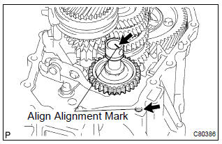
- Coat the reverse idler gear sub–assy, thrust washer and reverse idler gear shaft with gear oil, install them as shown in the illustration.
Hint
: align the mark on the reverse idler gear shaft with the bolt hole shown in the illustration.
75. Install gear shift fork shaft sub–assy no.1
- Coat the gear shift fork no.1 And gear shift fork no.2 With gear oil, install them.
- Coat the gear shift fork shaft sub–assy no.1 With gear oil, install it.
- apply sealant to the shift fork lock bolt.
Sealant:
part no. 08833–00080, Three bond 1344, loctite 242 or equivalent - install the gear shift fork lock bolt.
Torque: 15.7 Nvm (160 Kgf·cm, 12 ft·lbf)
- Using a brass bar and a hammer, install the shaft snap ring to the gear shift fork shaft no.1.
76. Install gear shift fork shaft no.3
- Coat the 2 balls with mp grease, install them to the reverse shift fork.
- install the reverse shift fork to the gear shift fork shaft no.3.
- Using a brass bar and a hammer, install the 2 shift fork shaft snap rings to the gear shift fork shaft no.3.
- Coat the gear shift fork shaft no.3 With gear oil, install it.
77. Install gear shift fork shaft no.2
- Coat the gear shift head no.1 And gear shift fork shaft no.2 With gear oil, install them.
Notice
: to avoid the interference of the 2 shift fork balls, lift up the gear shift fork shaft no.3 At the position shown in the illustration.
- Coat the 2 shift lock bolts with sealant, install then to the
gear shift fork no.2 And gear shift head no.1.
Sealant:
part no. 08833–00080, Three bond 1344, loctite 242 or equivalent
torque: 15.7 Nvm (160 Kgf·cm, 12 ft·lbf)

- Using a brass bar and a hammer, install the 2 shift fork shaft snap rings to the gear shift fork shaft no.3.
- Coat the gear shift fork shaft no.3 With gear oil, install it.
77. Install gear shift fork shaft no.2

- Coat the gear shift head no.1 And gear shift fork shaft no.2 With gear oil, install them.
Notice
: to avoid the interference of the 2 shift fork balls, lift up the gear shift fork shaft no.3 At the position shown in the illustration.
- Coat the 2 shift lock bolts with sealant, install then to the
gear shift fork no.2 And gear shift head no.1.
Sealant:
part no. 08833–00080, Three bond 1344, loctite 242 or equivalent
torque: 15.7 Nvm (160 Kgf·cm, 12 ft·lbf)
78. Install reverse shift arm bracket assy
- install the reverse shift arm bracket assy with 2 bolts to the
transaxle case.
Torque: 17.2 Nvm (175 Kgf·cm, 13 ft·lbf)
79. Install manual transmission case
- Apply fipg to the manual transmission case, as shown
in the illustration.
Fipg:
part no. 08826–00090, Three bond 1281 or equivalent
N
otice
: parts must be assembled within 10 minutes of application.
Otherwise, the packing (fipg) material must be removed and reapplied.
- Coat the 13 bolts with sealant, install them to the manual
transmission case.
Sealant:
part no. 08833–00080, Three bond 1344, loctite 242 or equivalent
torque: 29.4 Nvm (300 Kgf·cm, 22 ft·lbf)
- Coat the 3 bolts with sealant, install them to the transaxle
case.
Sealant:
part no. 08833–00080, Three bond 1344, loctite 242 or equivalent
torque: 29.4 Nvm (300 Kgf·cm, 22 ft·lbf)
80. Install reverse idler gear shaft bolt
- Coat the reverse idler gear shaft bolt with sealant, install
it with a new gasket.
Sealant:
part no. 08833–00080, Three bond 1344, loctite 242 or equivalent
torque: 29.4 Nvm (300 Kgf·cm, 22 ft·lbf)
81. Install lock ball assy no.1
- Coat the lock ball assy no.1 With sealant, install it with using
a hexagon wrench.
Sealant:
part no. 08833–00080, Three bond 1344, loctite 242 or equivalent
torque: 39.2 Nvm (400 Kgf·cm, 29 ft·lbf)
82. Install shift detent ball
- Install the 2 shift detent balls, 2 springs with 2 seats to the manual transmission case.

- Coat the 2 shift detent ball plugs with sealant, install them
with using a hexagon wrench.
Sealant:
part no. 08833–00080, Three bond 1344, loctite 242 or equivalent
torque: 24.5 Nvm (250 Kgf·cm, 18 ft·lbf)
- Install the shift detent ball, spring and seat to the transaxle case.
- Coat the shift detent ball plug with sealant, install it with
using a hexagon wrench.
Sealant:
part no. 08833–00080, Three bond 1344, loctite 242 or equivalent
torque: 24.5 Nvm (250 Kgf·cm, 18 ft·lbf)
83. Install input shaft rear bearing hole snap ring
- Using a snap ring expander, install the input shaft rear bearing hole snap ring to the input shaft.
84. Install output shaft rear bearing hole snap ring
- Using a snap ring expander, install the output shaft rear bearing hole snap ring to the output shaft.
85. Install shift fork shaft shaft snap ring
- Using a brass bar and a hammer, install the shift fork shaft shaft snap ring to the shift fork shaft no.2.
86. Install bearing retainer rear (mtm)
- Coat the 5 bolts with sealant, install them and bearing retainer
rear (mtm) to the manual transmission case.
Torque: 27.4 Nvm (279 Kgf·cm, 20 ft·lbf)
87. Install 5th driven gear
- Using sst, install the 5th driven gear to the output shaft.
Sst 09309–12020
88. Install 5th gear needle roller bearing
- Coat the 5th gear needle roller bearing and 5th gear bearing spacer with gear oil, install them to the input shaft.
89. Install 5th gear
- Coat the 5th gear with gear oil, install it to the input shaft.
90. Install synchronizer ring no.3
- Coat the synchronizer ring no.3 With gear oil, install it to the 5th gear.
91. Install transmission clutch hub no.3
- Install the 3 synchromesh shifting keys and 2 synchromesh shifting key springs to the transmission clutch hub no.3.
Hint
: do not set both openings of the shifting key springs in the same position.
- Using sst and a hammer, install the transmission clutch
hub no.3 To the input shaft.
Sst 09636–20010
Hint
:
- before driving in the no.3 Clutch hub assy, place the suitable sized wooden block on the rear side of the input shaft, as shown in the illustration.
- When driving it in, fix the input shaft firmly so that it is not pushed downward. Otherwise the input shaft rear bearing is over loaded, it might be damaged.
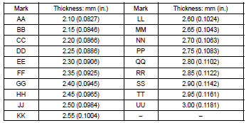
- Select a snap ring from the table below that will make the thrust clearance of the transmission clutch hub no.3 Below 0.1 Mm (0.0039 In.).
Snap ring thickness:
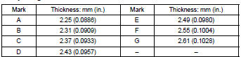
- Using a brass bar and a hammer, install the snap ring to the input shaft.
92. Inspect 5th gear thrust clearance
- Using a dial indicator, measure the 5th gear thrust clearance.
5Th gear thrust clearance:
93. Inspect 5th gear radial clearance
- Using a dial indicator, measure the 5th gear radial clearance.
5Th gear radial clearance:
If the clearance exceed the maximum value, replace the gear, needle roller bearing or shaft.
94. Install gear shift fork no.3
- Coat the transmission clutch hub sleeve no.3 With gear oil, install it and gear shift fork no.3 To the transmission clutch hub no.3.
Hint
: do not set the transmission clutch hub no.3 In incorrect orientation.
- Coat the gear shift lock fork ball with sealant, install it to
the gear shift fork no.3.
Sealant:
part no. 08833–00080, Three bond 1344, loctite 242 or equivalent
torque: 15.7 Nvm (160 Kgf·cm, 12 ft·lbf)
95. Install manual transmission output shaft rear set nut
- Engage the gear double meshing.
- install a new manual transmission output shaft rear set
nut.
Torque: 117.6 Nvm (1,200 Kgf·cm, 87 ft·lbf)
- Using a chisel and a hammer, stake the manual transmission output shaft rear set nut.
- disengage the gear double meshing.
96. Install manual transmission case cover sub–assy
- Apply fipg to the manual transmission case cover sub–
assy as shown in the illustration.
Fipg: part no. 08826–00090, Three bond 1281 or equivalent
Notice
: parts must be assembled within 10 minutes of application.
Otherwise, the packing (fipg) material must be removed and reapplied.
- Install the manual transmission case cover sub–assy with
the 9 bolts to the manual transmission case.
Torque: 18.1 Nvm (185 Kgf·cm, 14 ft·lbf)
97. Install shift & select lever shaft assy
- Coat the 4 bolts with sealant, install them, new gasket and shift & select lever shaft assy to the manual transmission case.
Sealant:
part no. 08833–00080, Three bond 1344, loctite
242 or equivalent
torque: 19.6 Nvm (200 Kgf·cm, 14 ft·lbf)
Notice
: set the claws of the shift interlock plate into the shift head part of the gear shift fork shaft securely.
98. Install lock ball assy no.1
- Coat the lock ball assy no.1 With sealant, install it to the
manual transmission case.
Sealant:
part no. 08833–00080, Three bond 1344, loctite 242 or equivalent
torque: 29.4 Nvm (300 Kgf·cm, 22 ft·lbf)
99. Install selecting bell crank assy
- Install the selecting bellcrank assy with control shift lever
bush with the 2 bolts to the manual transmission case.
Torque: 24.5 Nvm (250 Kgf·cm, 18 ft·lbf)
Notice
: apply mp grease to the inside circumferential surface of the control shift lever bush (a).
100. Install floor shift control lever housing support bracket
- Install the floor shift control lever housing support bracket
with the 3 bolts to the transaxle case.
Torque: 11.3 Nvm (115 Kgf·cm, 8 ft·lbf)
101. Install back up lamp switch assy
- Using sst, install the backup lamp switch assy with a new
gasket to the manual transmission case.
Torque: 40.2 Nvm (410 Kgf·cm, 30 ft·lbf) sst 09817–16011
102. Install speedometer driven hole cover sub–assy (w/ abs)
- install a new o–ring to the speedometer driver hole cover sub–assy.
- install the speedometer driver hole cover sub–assy with the bolt.
Torque: 11.3 Nvm (115 Kgf·cm, 8 ft·lbf)
103. Install speedometer driven (mtm) gear sub–assy (w/o abs)
- install the speedometer driven (mtm) gear sub–assy with clip to the speedometer sensor.
104. Install speedometer sensor (w/o abs)
- install a new o–ring to the speedometer sensor.
- install the speedometer sensor with the bolt.
Torque: 11.3 Nvm (115 Kgf·cm, 8 ft·lbf)
105. Install release fork support
- Install the release fork support to the transaxle case.
Torque: 36.8 Nvm (375 Kgf·cm, 25 ft·lbf)
106. Install clutch release fork boot
- Install the clutch release fork boot to the transaxle case.
107. Install clutch release bearing assy
- Coat the clutch release bearing assy with the release hub grease, install it to the clutch release fork sub–assy.
Sealant:
part no. 08887–01806, Release hub grease or
equivalent
108. Install clutch release fork sub–assy
- Install the clutch release fork sub–assy to the input shaft.
- apply clutch spline grease to spline of the input shaft.
Sealant:
part no. 08887–01806, Clutch spline grease or
equivalent
109. Install drain (mtm) plug sub–assy
- Install a new gasket with the drain (mtm) plug sub–assy.
Torque: 39.2 Nvm (400 Kgf·cm, 29 ft·lbf)
110. Install manual transmission filler plug
- Install a new gasket with the manual transmission filler
plug.
Torque: 39.2 Nvm (400 Kgf·cm, 29 ft·lbf)


Other materials:
On–vehicle inspection
1. Inspection throttle body idle speed control valve assy
Notice:
it is impossible to check the resister value and the operation
of isc valve by itself, because the isc valve
has an ic circuit inside it, which transforms the duty
signal from the ecm to the derive signal.
After check ...
Inspection procedure
1 Check door lock
When the door does not operate manually, proceed to ”a”.
when the door does not operate via the key, proceed to ”b”.
2 Inspect door lock control switch
W/ power window:
remove the power window regulator master switch assy.
Inspect th ...
On–vehicle inspection
1. Connect hand–held tester:
connect the hand–held tester to the dlc3.
start the engine and run it at idle.
select the active test mode on the hand–held tester.
Hint:
please refer to the hand–held tester operator’s manual for further details.
2. Inspect actua ...