Toyota Corolla (E120): Overhaul
1. Remove w/head taper screw plug no.2
- Using a socket hexagon wench 10, remove the taper screw plug and gasket.
2. Remove valve lifter
- Remove the valve lifters from the cylinder head.
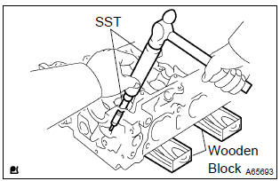
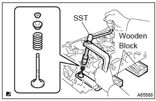
3. Remove valve
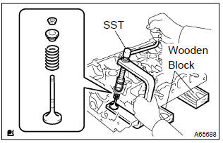
- Place the cylinder head on wooden blocks.
- using sst, compress the inner compression spring and
remove the 2 valve spring retainer locks.
Sst 09202–70020 (09202–00010, 09202–01010, 09202–01020)
- remove the valve spring retainers, inner compression springs and valves from the cylinder head.
4. Valve stem oil o seal or ring
- Using a needle–nose pliers, remove the valve stem oil seals.
5. Remove valve spring seat
- Using a compressed air and a magnetic finger, remove the valve spring seats.
6. Remove stud bolt
- Using torx socket wrench e5 and e7, remove the 11 stud bolts.
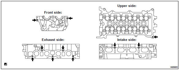
7. Inspect cylinder head for flatness
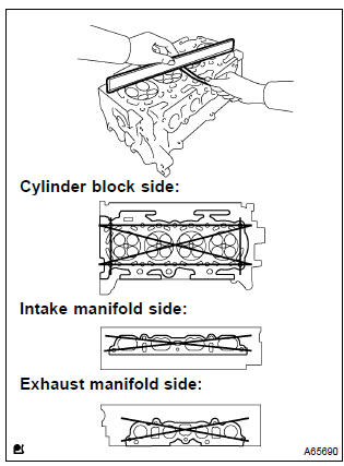
- Using a precision straight edge and a feeler gauge, measure
the surface contacting the cylinder block and the
manifolds for warpage.
Maximum warpage:
cylinder block side 0.05 Mm (0.0020 In.) Intake manifold side 0.10 Mm (0.0039 In.) Exhaust manifold side 0.10 Mm (0.0039 In.)
If the warpage is greater than maximum, replace the cylinder head.
8. Inspect cylinder head for cracks
- Using a dye penetrate, check the combustion chamber, intake ports, exhaust ports and cylinder block surface for cracks.
9. Inspect valve seats
- Apply a light coat of prussian blue (or white lead) to the valve face.
- lightly press the valve against the seat.
Notice
: do not rotate valve.
- check the valve face and seat according to the following procedure.
- If blue appears 360 around the face, the valve is concentric. If not, replace the valve.
- If blue appears 360 around the valve seat, the guide and face are concentric. If not, resurface the seat.
- Check that the seat contact is in the middle of the valve face with the width between 1.0 – 1.4 Mm (0.039 – 0.055 In.).
10. Repair valve seats
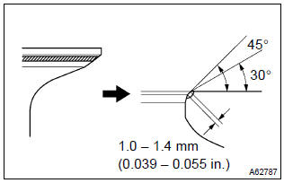
Notice
: take off a cutter gradually to make smooth valve seats.
- if the seating is too high on the valve face, use 30 and 45 cutters to correct the seat.
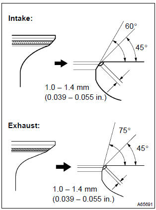
- Intake:
- if the seating is too low on the valve face, use 60 and 45 cutters to correct the seat.
- exhaust:
- if the seating is too low on the valve face, use 75 and 45 cutters to correct the seat.
- hand–lap the valve and valve seat with an abrasive compound.
- check the valve seating position.
11. Inspect camshaft thrust clearance
- Install the 2 camshafts.
- using a dial indicator, measure the thrust clearance while
moving the camshaft back and forth.
Standard thrust clearance: 0.040 – 0.095 Mm (0.0016 – 0.0037 In.) Maximum thrust clearance: 0.110 Mm (0.0043 In.)
If the thrust clearance is greater than maximum, replace the cylinder head. If damages are found on the camshaft thrust surfaces, the camshaft also has to be replaced.
12. Inspect camshaft oil clearance
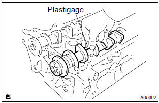
- Clean the bearing caps and camshaft journals.
- place the camshafts on the cylinder head.
- lay a strip of plastigage across each of the camshaft journal.
- install the bearing caps.
N
otice
: do not turn the camshaft.
- remove the bearing caps.
- Measure the plastigage at its widest point.
Standard oil clearance: 0.035 – 0.072 Mm (0.0014 – 0.0028 In.) Maximum oil clearance: 0.10 Mm (0.0039 In.)
Notice
: completely remove the plastigage after the measuring.
If the oil clearance is greater than maximum, replace the cylinder head.
13. Inspect valve lifter
- Using a micrometer, measure the valve lifter diameter.
Lifter diameter: 30.966 – 30.976 Mm (1.2191 – 1.2195 In.)
14. Inspect valve lifter oil clearance
- Using a caliper gauge, measure the valve lifter bore diameter
of the cylinder head.
Lifter bore diameter:
31.000 – 31.025 Mm (1.2205 – 1.2215 In.) - subtract the valve lifter diameter measurement from the
valve lifter bore diameter measurement.
Standard oil clearance: 0.024 – 0.059 Mm (0.0009 – 0.0023 In.) Maximum oil clearance: 0.079 Mm (0.0031 In.)
If the oil clearance is greater than maximum, replace the valve lifter.
If necessary, replace the cylinder head.
15. Inspect inner compression spring
- Using a vernier caliper, measure the free length of the inner
compression spring.
Free length: 43.40 Mm (1.7087 In.)
- Using a steel square, measure the deviation of the
inner
compression spring.
Maximum deviation: 1.6 Mm (0.063 In.) Maximum angle (reference): 2
if the deviation is greater than maximum, replace the inner compression spring.
- Using a spring tester, measure the tension of the inner
compression spring at the specified installed length.
Installed tension:
158.6 – 175.4 N (16.2 – 17.9 Kgf, 35.7 – 39.5 Lbf) at 33.6 Mm (1.323 In.)
Maximum working tension: 335.3 – 370.7 N (34.2 – 37.8 Kgf, 75.4 – 83.3 Lbf) at 24.1 Mm (0.949 In.)
If the installed tension is not as specified, replace the inner compression spring.
16. Inspect valve
- Using a vernier calipers, check the valve overall length.
Standard overall length: intake 88.65 Mm (3.4902 In.) Exhaust 88.69 Mm (3.4917 In.) Minimum overall length: intake 88.35 Mm (3.4784 In.) Exhaust 88.39 Mm (3.4799 In.)
If the overall length is less than minimum, replace the valve.
- Using a micrometer, measure the diameter of the valve
stem.
Valve stem diameter:
intake 5.470 – 5.485 Mm (0.2154 – 0.2159 In.) Exhaust 5.465 – 5.480 Mm (0.2152 – 0.2158 In.)

- Using a vernier calipers, check the valve head margin
thickness.
Standard margin thickness: 1.0 Mm (0.039 In.) Minimum margin thickness: 0.7 Mm (0.028 In.)
If the overall length is less than minimum, replace the valve.
17. Inspect valve guide bushing oil clearance
- Using a caliper gauge, measure the inside diameter of the
valve guide bush.
Busing inside diameter: 5.510 – 5.530 Mm (0.2169 – 0.2177 In.)
- Subtract the valve stem diameter measurement from the
guide bushing inside diameter measurement.
Standard oil clearance: intake 0.025 – 0.060 Mm (0.0010 – 0.0024 In.) Exhaust 0.030 – 0.065 Mm (0.0012 – 0.0026 In.) Maximum oil clearance:
intake 0.08 Mm (0.0032 In.) Exhaust 0.10 Mm (0.0039 In.)
If the oil clearance is greater than maximum, replace the valve and valve guide bushing.
18. Replace valve guide bushing
- heat the cylinder head to 80 – 100 c (176 – 212 f).
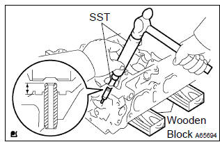
- Place the cylinder head on the wooden blocks.
- using sst, tap out the valve guide bushing.
Sst 09201–10000, 09201–01055, 09950–70010 (09951–07100)
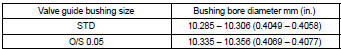
- Using a caliper gauge, measure the bushing bore diameter
of the cylinder head.
Diameter: 10.285 – 10.306 Mm (0.4049 – 0.4058 In.)
If the bushing bore diameter of the cylinder head is greater than 10.306 Mm (0.4058 In.), Machine the bushing bore to the dimension of 10.335 – 10.356 Mm (0.4069 – 0.4077 In.) To install a over size valve guide bushing.
Hint:
- Heat the cylinder head to 80 – 100 c (176 – 212 f).
- Place the cylinder head on wooden blocks.
- using sst, tap in a new valve guide bushing to the specified
protrusion height.
Sst 09201–10000, 09201–01055, 09950–70010 (09951–07100)
protrusion height: 8.7 – 9.1 Mm (0.343 – 0.358 In.)
- Using a sharp 5.5 Mm reamer, ream the valve guide bushing
to obtain the standard specified clearance.
Standard oil clearance: intake 0.025 – 0.060 Mm (0.0010 – 0.0024 In.) Exhaust 0.030 – 0.065 Mm (0.0012 – 0.0026 In.)
19. Install straight pin
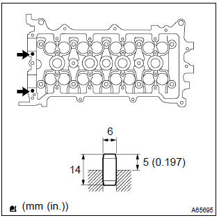
- Using a plastic hammer, install the new 2 straight pins.
Standard protrusion: 5 mm (0.197 In.)
20. Install union
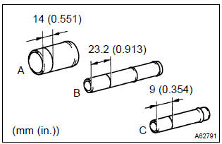
- Mark the standard position away from the edge, onto the water hose union as shown in the illustration.
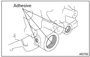
- Apply adhesive to the water hose union hole of the cylinder
head.
Adhesive:
part no. 08833–00070, Three bond 1324 or equivalent.
- Using a press, press in a new water hose union until the
standard marks come to the level of the cylinder head surface.
Standard protrusion:
a 29 mm (1.142 In.)
B 66.5 Mm (2.618 In.)
C 24 mm (0.945 In.)
Notice
:
- install the water hose union within 3 minutes after applying adhesive.
- Do not put into coolant within an hour after installing.
21. Install stud bolt
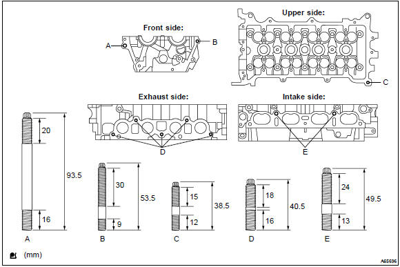
- Using torx socket wrench e5 and e7, install the 11 stud bolts,
torque:
stud bolt a, d and e 9.5 Nvm (97 Kgf·cm, 84 in.Vlbf) stud bolt b and c 5.0 Nvm (51 Kgf·cm, 44 in.Vlbf)
22. Install valve spring seat
- Install the valve spring seats to the cylinder head.
23. Install valve stem oil o seal or ring
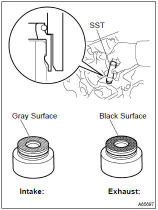
- Apply a light coat of engine oil to a new valve stem oil
seals.
Notice
: be very careful to assemble the oil seal for intake and exhaust.
Assembling the wrong one may cause a failure.
Hint
: the intake valve stem oil seal is gray and exhaust valve stem oil seal is black.
- using sst, push in the valve stem oil seals.
Sst 09201–41020
24. Install valve
- Place the cylinder head on wooden blocks.
- install the valves, inner compression springs and valve spring retainers to the cylinder head.
- using sst, compress the inner compression spring, and
place the 2 valve spring retainer locks around the valve
stem.
Sst 09202–70020 (09202–00010, 09202–01010, 09202–01020)
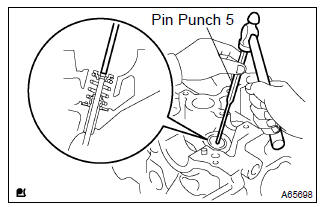
- Using a pin punch 5, lightly tap the valve stem tip to ensure a proper fit.
Notice
: be careful not to damage the valve stem tip.
25. Install valve lifter
- Apply a light coat of engine oil to the valve lifters.
- install the valve lifters to the cylinder head.
26. Install w/head taper screw plug no.2
- Using a socket hexagon wrench 10, install the taper
screw plug with a new gasket.
Torque: 44 nvm (449 Kgf·cm, 33 ft·lbf)


Other materials:
Glossary of sae and toyota terms
This glossary lists all sae–j1930 terms and abbreviations used in this manual
in compliance with sae recommendations,
as well as their toyota equivalents.
...
Circuit description
The vapor pressure sensor, vsv for canister closed valve (ccv), vsv for
pressure switching valve are used
to detect abnormalities in the evaporative emission control system.
The ecm decides whether there is an abnormality in the evaporative emission
control system based on the
vapor pressur ...
Taking out the spare tire
1 Remove the luggage floor cover.
2 Remove the tool tray.
3 Loosen the center fastener that secures the spare tire.
CAUTION
■When storing the spare tire
Be careful not to catch fingers or other body parts between the spare tire and
the body of the vehicle. ...