Toyota Corolla (E120): Overhaul
1. Remove oil pump relief valve
- Remove the oil pump relief valve plug, oil pump relief valve spring and oil pump relief valve.
- Oil pump relief valve plug
- oil pump relief valve spring
- oil pump relief valve
2. Inspect oil pump assy
- Remove 3 screws and oil pump cover.
- Inspect the oil pump relief valve.
- Coat the valve with engine oil and check that it falls smoothly into the valve hole by it own weight.
- inspect the oil pump rotor sub–assembly.
- Coat the oil pump gear set with engine oil and place them into the oil pump body. Check that the rotors revolves smoothly.
- inspect rotor tip clearance.
- Using a feeler gauge, measure the clearance between
the drive and driven rotor tips.
Standard tip clearance: 0.040 – 0.160 Mm (0.0016 – 0.0063 In.)
- Inspect body clearance.
- Using a feeler gauge, measure the clearance between
the driven rotor and body.
Standard body clearance: 0.260 – 0.325 Mm (0.0102 – 0.0128 In.)
- Inspect rotor side clearance.
- Using a feeler gauge and precision straight edge,
measure the clearance between the rotors and precision
straight edge.
Standard side clearance: 0.025 – 0.071 Mm (0.0010 – 0.0028 In.)
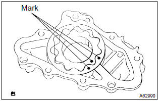
- Install oil pump rotor sub–assembly.
- Coat the oil pump gear set with engine oil and place it into pump body with the marks facing the pump body cover side.
- Install oil pump rotor sub–assembly.
(1) Coat the oil pump gear set with engine oil and place it into pump body with the marks facing the pump body cover side.
3. Install oil pump relief valve
- Install the oil pump relief valve plug, oil pump relief valve
spring and oil pump relief valve.
Torque: 37 nvm (375 Kgf·cm, 27 ft·lbf)
- oil pump relief valve plug
- oil pump relief valve spring
- oil pump relief valve


Other materials:
Tire size
■ Typical tire size information
The illustration indicates typical tire size.
1 Tire use (P = Passenger car, T = Temporary use)
2 Section width (millimeters)
3 Aspect ratio (tire height to section width)
4 Tire construction code (R = Radial, D = Diagonal)
5 Wheel diameter (inches)
6 Loa ...
Using a flat bed truck
If you use chains or cables to tie down your vehicle, the angles shaded in black
must be 45°.
Do not overly tighten the tie downs or the vehicle may be damaged.
■Before emergency towing
1 Vehicles without a smart key system: Put the engine switch in the “ACC” (engine
off) or “O ...
About this vehicle
1. Structural outline
2. Notice about vehicle condition when jacking up
vehicle
(a) notice for using jack and safety stand
(B) notice for using swing arm type lift
(C) notice for using plate type lift
3. Damage diagnosis
4. Components
(a) front bumper
(B) side mu ...