Toyota Corolla (E120): On–vehicle inspection
1. Inspect turn signal flasher relay circuit
- Disconnect the connector from the turn signal flasher relay and inspect the connector on wire harness side as shown in the chart.
Standard:
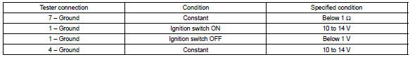
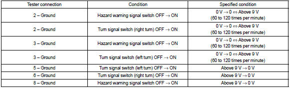
- Connect the connector to the turn signal flasher and inspect the wire harness side connector from the back side as shown in the chart.
Standard:
2. Inspect daytime running light relay
- Connect the connector to the daytime running light relay and inspect the wire harness side connector from the back side as shown in the table below.
Standard:
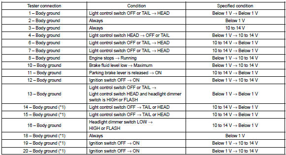
*1: Usa only.
3. Illuminated entry system operation check
- the illuminated entry system controls the room lamp assy no.1.
- check that the lamps come on when any of the doors are opened. Then check that the lamps fade out under any one of the following conditions:
- 15 seconds after all the doors are closed.
- The ignition switch is turned to the on position with all the doors closed.
- All the doors are closed and locked.
- check that the lamps stay on for at least 15 seconds after opening any of the doors before fading out as described in (b). Then check that the lamps fade out in 15 seconds after closing all the doors.
- check that the lamps come on when opening any of the doors and fade out when closing and locking all the doors or turning the ignition switch to the acc or on position.
4. Battery saver operation check
- remove the ignition key and close all the doors.
- open any door to turn the room light on, and leave it open. Check
that the light goes off after approx.
20 Minutes.
- after the room light goes off, close the door.
- open any door to turn the room light on, and then open another door. Check that the room light goes off after approx. 20 Minutes after opening the doors.
- close all the doors. With the ignition key inserted, open any door to turn the room light on, and then remove the ignition key. Check that the room light goes off after approx. 20 Minutes.


Other materials:
Circuit description
When the brake pedal is depressed, the stop lamp switch assy sends a signal
to the cruise control ecu assy.
When the cruise control ecu assy receives this signal, it cancels the cruise
control.
A fail–safe function is provided so that cancel functions normally, even if
there is a malfu ...
Anti-glare function
► Manual anti-glare inside rear view mirror
Reflected light from the headlights of vehicles behind can be reduced by operating
the lever.
1 Normal position
2 Anti-glare position
► Auto anti-glare inside rear view mirror
Responding to the level of brightness of the headlights of ...
Circuit description
The throttle position sensor is mounted in the throttle body and
detects the throttle valve opening angle.
When the throttle valve is fully closed, a voltage of approximately
0.3 To 1.0 V is applied to terminal vta of the ecm. The voltage
applied to terminal vta of the ecm increases in pro ...