Toyota Corolla (E120): Inspection
1. Headlamp dimmer switch assy
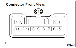
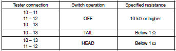
- Inspect light control switch continuity.
- Measure the resistance according to the value(s) in the table below.
Standard:
- Inspect headlight dimmer switch continuity.
- Measure the resistance according to the value(s) in the table below.
Standard:
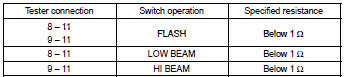
Hint
: turn light control switch to the head position when checking ”low beam” and ”hi beam”.
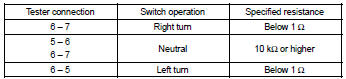
- inspect turn signal switch continuity.
- Measure the resistance according to the value(s) in the table below.
Standard:
- W/ fog light: inspect front fog light switch continuity.
- Measure the resistance according to the value(s) in the table below.
Standard:
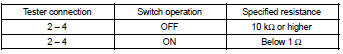
2. Back up lamp switch assy
- measure the resistance according to the value(s) in the table below.
Standard:

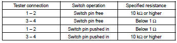
3. Stop lamp switch assy (w/o cruise control)
- measure the resistance according to the value(s) in the table below.
Standard:

4. Stop lamp switch assy (w/ cruise control)
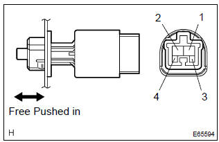
- Measure the resistance according to the value(s) in the table below.
Standard:
5. Hazard warning signal switch assy
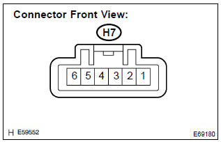
- Measure the resistance according to the value(s) in the table below.
Standard:
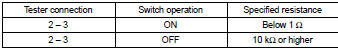
- Inspect illumination operation.
- Connect the positive (+) lead from the battery to terminal 5 and the negative (–) lead to terminal 4, then check that the illumination comes on.
6. Front door courtesy lamp switch assy
- measure the resistance according to the value(s) in the table below.
Standard:

7. Rear door courtesy lamp switch assy
- measure the resistance according to the value(s) in the table below.
Standard:

8. Luggage compartment room courtesy lamp switch assy
- measure the resistance according to the value(s) in the table below.
Standard:

9. Map lamp assy (w/o sliding roof)
- Measure the resistance according to the value(s) in the table below.
Standard:

- Connect the positive (+) lead from the battery to terminal 1 and the negative (–) lead to terminal 6, then check that the illumination comes on when switch operation is on position.
10. Map lamp assy (w/ sliding roof)
- Measure the resistance according to the value(s) in the table below.
Standard:
- Connect the positive (+) lead from the battery to terminal 1 and the negative (–) lead to terminal 3, then check that the illumination comes on when switch operation is on position.
11. Room lamp assy no.1
- Connect the positive (+) lead from the battery to terminal 1 and the negative (–) lead to terminal 2, then check that the illumination comes on .
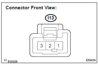
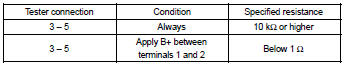
13. Headlamp relay
- Measure the resistance according to the value(s) in the table below.
Standard:
14. Fog lamp relay

- Measure the resistance according to the value(s) in the table below.
Standard:

15. Taillamp relay
- Measure the resistance according to the value(s) in the table below.
Standard:
16. Headlamp dimmer relay
- Measure the resistance according to the value(s) in the table below.
Standard:
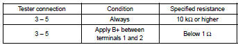
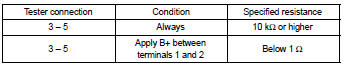
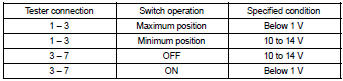
17. Light control rheostat
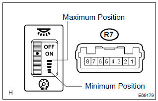
- Connect the connector to the rheostat and inspect the wire harness side connector from the back side as shown in the table below.
Standard:
- Inspect illumination operation.
- Connect the positive (+) lead from the battery to terminal 2 and the negative (–) lead to terminal 3, then check that the illumination comes on.


Other materials:
Floor shift parking lock cable assy (atm)
Replacement
1. Precaution
2. Disconnect battery negative terminal
3. Place front wheels facing straight ahead
4. Remove horn button assy
5. Remove steering wheel assy
sst 09950–50013 (09951–05010, 09952–05010, 09953–05020, 09954–05021)
6. Remove steering column cover
7. Remove c ...
Inspection procedure
Hint:
if dtcs besides misfire are memorized simultaneously, first perform
the troubleshooting for them.
Read freeze frame data using the hand-held tester or the obd ii scan
tool. Freeze frame data records
the engine conditions when a malfunction is detected. When troubleshooting,
it ...
On–vehicle inspection
Notice:
”cold” and ”hot” in these sentences express the temperature of the coils
themselves. ”Cold” is from
–10 c (14 f) to 50 c (122 f) and ”hot” is from 50 c (122 f) to 100 c (212 f).
1. Inspect ignition coil (with igniter) and spark test
confirm dtc.
Notice:
...