Toyota Corolla (E120): Inspection
1. Intake air flow meter sub–assy
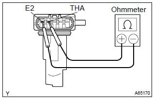
- Inspect the intake air flow meter resistance.
- Using an ohmmeter, measure the resistance between terminals tha and e2.
Resistance:
at –20 c (–4 f) 13.6 To 18.4 KΩ
at 20 c (68 f) 2.21 To 2.69 KΩ
at 60 c (140 f) 0.49 To 0.67 KΩ
Hint
: if the resistance is not as specified, replace the intake air flow meter.
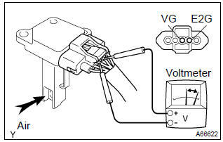
- Inspect the intake air flow meter operation.
- Connect the intake air flow meter connector.
- Turn the ignition switch to on.
- Using a voltmeter, connect the positive (+) tester probe to terminal vg, and negative (–) tester probe to terminal e2g.
- Blow air into the intake air flow meter, and check that
the voltage fluctuates.
Hint
: if operation is not as specified, replace the intake air flow meter.
- Turn the ignition switch to lock.
- Disconnect the intake air flow meter connector.
2. Camshaft timing oil control valve assy
- resistance inspection.
- Using an ohmmeter, measure the resistance between
the terminals.
Resistance: 6.9 To 7.9 W at 20 c (68 f)
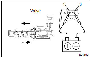
- Movement inspection.
- Connect the positive (+) lead from the battery to terminal 1 and negative (–) lead to terminal 2, and check the movement of the valve.
Notice
: confirm the valve does not adhere.
Hint
: bad returning of the valve by entrance of foreign objects causes subtle pressure leak to the advanced direction. Then, dtc can be detected.
3. Throttle body assy
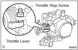
- Check throttle body.
- Check that throttle valve shaft is not rickety.
- Check that each port is not stopped up.
- Check that throttle valve opens and closes smoothly.
- Check that there is no clearance between the throttle stop screw and throttle lever at the throttle closed position.
Notice
: do not adjust the throttle stop screw.
4. E.F.I. Throttle position sensor
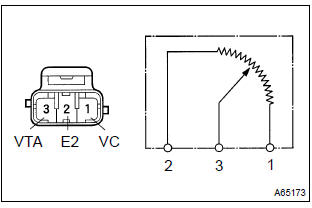
- Resistance inspection.
- Disconnect the throttle position sensor connector.
- Using an ohmmeter, measure the resistance between
terminals vc and e2.
Resistance: 2.5 To 6.0 KΩ
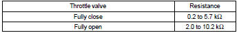
- check the change of resistance between terminals vta and e2.
Change of resistance: the resistance value increases in proportion to the throttle lever opening value.
Hint:
5. E.F.I. Engine coolant temperature sensor
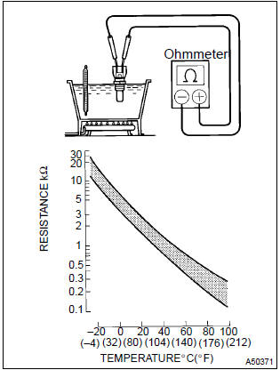
- Resistance inspection.
- Using an ohmmeter, measure the resistance between each terminal.
Resistance:
at 20 c (68 f) 2.32 – 2.59 KΩ
at 80 c (176 f) 0.310 – 0.326 KΩ
Notice
: in case of checking the water temperature sensor in the water, be careful not to allow water to go into the terminals, and after checking, wipe out the sensor.
6. Knock control sensor
- Using an ohmmeter, measure the resistance between terminals.
Resistance: 120 – 280 kΩ at 20 c (68 f)
Hint
: if the resistance is not specified, replace the sensor.
7. E.F.I. Circuit opening relay assy
- Continuity inspection.
- Using an ohmmeter, check that continuity exists between
each terminal.
Specified condition:
between terminals 1 and 2 continuity between terminals 3 and 5 no continuity - using an ohmmeter, check that continuity exists between terminals 3 and 5 when the battery voltage is applied across terminals 1 and 2.
8. E.F.I ecu relay
- Continuity inspection.
- Using an ohmmeter, check that continuity exists between
each terminal.
Specified condition:
between terminals 1 and 2 continuity between terminals 3 and 5 no continuity - using an ohmmeter, check that continuity exists between terminals 3 and 5 when the battery voltage is applied across terminals 1 and 2.


Other materials:
Child restraint systems with a top tether strap
1 Adjust the head restraint to the downmost position.
2 Secure the child restraint system using the seat belt or LATCH anchors.
3 Open the anchor bracket cover, latch the hook onto the anchor bracket and tighten
the top tether strap.
Make sure the top tether strap is securely latched.
` ...
Basic Audio Operations
Basic audio operations and functions common to each mode are explained in
this section.
Operating the multimedia system
Random playback
Select to change on/off.
Repeat play
Select to change on/off.
■Using cellular phones
Interference may be heard through the multimedia system' ...
Inspection
1. Charcoal canister assy
Visually check the charcoal canister for cracks or damage.
Inspect the charcoal canister operation.
Plug the vent port with the cap.
While holding the purge port closed, blow air (1.76
Kpa, 18 gf/cm2, 0.26 Psi) into the evap port and
...