Toyota Corolla (E120) 2002–2008 Repair Manual / Engine control system / Throttle body assy
Toyota Corolla (E120): Throttle body assy
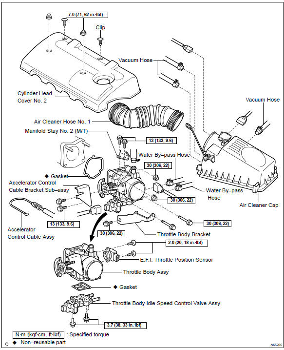
Components
Removal & installation and disassembly & reassembly
1. Drain coolant
2. Remove cylinder head cover no.2
- Remove 2 nuts, 2clips and the cylinder head cover no. 2.
3. Remove air cleaner cap sub–assy
- Disconnect the maf connector.
- disconnect the vsv connector.
- disconnect 3 vacuum hoses, as shown in the illustration.
- loosen an air cleaner hose clump and disconnect an air cleaner hose no. 1.
- remove the air cleaner cap.
4. Remove air cleaner hose no.1
5. Separate accelerator control cable assy
6. Remove throttle body assy
- Disconnect an throttle position sensor connector.
- disconnect a throttle body isc valve assy connector.
- disconnect a pcv hose.
- Disconnect 2 water by–pass hoses.
- Remove 5 bolts, 2 nuts, throttle body bracket and throttle body. (Transaxle m/t)
- Remove 3bolts, 2nuts and throttle body. (Transaxle a/t)
- Remove 2 bolts and accelerator cable bracket.
7. Remove E.F.I. Throttle position sensor
- Remove 2 screws and the throttle position sensor as shown in the illustration.
8. Remove thlottle body idle speed controlvalve assy
- Remove 3 screws and the idle speed control valve assy.
- remove the gasket from the throttle body.
9. Install thlottle body idle speed control valve assy
- Install a new gasket on the throttle body.
- install the idle speed control valve assy with 3 screws.
Torque: 3.7 Nvm (38 kgf·cm, 33 in.Vlbf)
10. Install E.F.I. Throttle position sensor
- Check that the throttle valve is fully close.
- insert the throttle position sensor to the throttle body with it turned counterclockwise by 30 to 90 against the fully close valve position.
- by turning the throttle position sensor clockwise, tighten
2 screws.
Torque: 2.0 Nvm (20 kgf·cm, 18 in.Vlbf)
11. Install throttle body assy
- Install the accelerator control bracket with 2 bolts.
Torque: 13 nvm (133 kgf·cm, 9.6 Ftvlbf)
- Install a new gasket on the intake manifold, as shown in the illustration.
- Install the throttle body with 5 bolts and 2 nuts.(Transaxle
m/t)
torque:
a 30 nvm (306 kgf·cm, 22 ftvlbf) b 13 nvm (133 kgf·cm, 9.6 Ftvlbf)
- Install the throttle body with 3 bolts and 2 nuts.(Transaxle a/t) torque: 30 nvm (306 kgf·cm, 22 ftvlbf)
- Connect 2 water by–pass hoses to the throttle body.
- Connect the pcv hose to the throttle body.
- connect the throttle body idle speed control valve assy connector to the throttle body.
- connect the throttle position sensor connector to the throttle body.
12. Install air cleaner cap sub–assy
- Install the air cleaner cap.
- connect the air cleaner hose.
- Connect 3 vacuum hoses, as shown in the illustration.
- connect the vsv connector.
- connect the intake air flow meter connector.
13. Install cylinder head cover no.2
- Install the cylinder head cover no. 2 With 2 nuts and 2
clips.
Torque: 7.0 Nvm (71 kgf·cm, 62 in.Vlbf)
14. Add coolant
15. Check engine coolant leak


Other materials:
Precaution
1. Precaution of headlight bulb replacement
if even a thin film of oil is left on the surface of the halogen
lamp, its service life will be shortened because
the lamp will be burn at a higher temperature.
handle any halogen lamp with great care. Dropping, hitting or
damagin ...
Replacement
Hint:
installation is in the reverse order of the removal. But the installation is
indicated only when it has a point.
1. Remove radiator grille sub–assy
Remove the 2 bolts and clip.
using a screwdriver, remove the radiator grille.
Hint:
tape the screwdriver tip before use. ...
Odometer and trip meter
display
■ Changing the display
Press the display change button
until the desired item is displayed.
■ Display items
Odometer
Displays the total distance the vehicle
has been driven.
Trip meter A/Trip meter B
Displays the distance the vehicle
has been driven since the meter
was last reset. Trip me ...