Toyota Corolla (E120) 2002–2008 Repair Manual / Engine control system / Ecm (1zz–fe)
Toyota Corolla (E120): Ecm (1zz–fe)
Replacement
1. Disconnect battery negative terminal
2. Remove glove compartment door assy
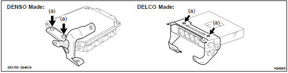
3. Remove ecm
- Remove the 2 clips using a clip remover. Then, open the cover.
- Disconnect the 4 ecm connectors.
- remove the wire harness from the wire harness clamp.
- Remove the 2 bolts.
- unfasten the claw and clip, then remove the ecm.
4. Remove ecm cover
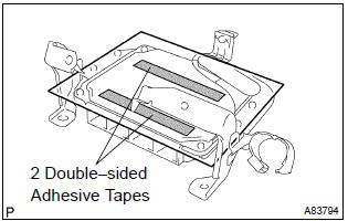
- Take the 2 double–sided adhesive tapes off the ecm, then remove the ecm cover.
5. Remove ecm bracket no.2 (Denso made)
- Remove the 2 screws, then remove the ecm bracket no.
2.
6. Remove ecm bracket no.1
- Remove the 2 screws, then remove the ecm bracket no.
7. Remove ecm bracket no.3 (Delco made)
- Remove the 2 screws, then remove the ecm bracket no.
8. Install ecm bracket no.3 (Delco made) torque: 3.2 Nvm (33 kgfvcm, 28 in.Vlbf)
9. Install ecm bracket no.1 Torque: 3.2 Nvm (33 kgfvcm, 28 in.Vlbf)
10. Install ecm bracket no.2 (Denso made) torque: 3.2 Nvm (33 kgfvcm, 28 in.Vlbf)
11. Install ecm cover
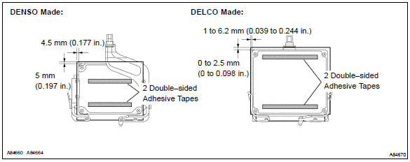
- Install a new ecm cover to the ecm as shown in the illustration.
12. Install ecm torque: 3.0 Nvm (31 kgfvcm, 27 in.Vlbf)
13. Install glove compartment door assy
14. Connect battery negative terminal torque: 5.4 Nvm (55 kgfvcm, 48 in.Vlbf)
15. Reset memory (a/t transaxle)
Caution
: perform the reset memory (at initialization) when replacing the ecm, engine assembly or automatic transaxle assembly.
- The hand–held tester only.
- Connect the hand–held tester to the dlc3.
- Turn the ignition switch on.
- Perform the reset memory procedure from the engine menu.
Caution
: after performing the reset memory, be sure to perform the road test as described earlier.


Other materials:
Inspection procedure
1 Check low pitched horn assy
Connect the positive (+) lead from the battery to the terminal
and negative (–) lead to the horn body, and check that
the horn blows.
2 Check relay (marking: horn)
Remove the relay from the engine room j/b.
check the horn relay conti ...
Dialing from the contacts list
You can dial a number from the contact data imported from your cellular phone.
The system has one contact for each registered phone. Up to 2500 contacts may be
stored in each contact. 1 Display the phone screen.
2 Select “Contacts” tab.
3 Choose the desired contact to call from the list.
...
Seat heaters
Press the switch.
1 High temperature
2 Low temperature
The indicator light comes on when the switch is on.
■The seat heaters can be used when
► Vehicles without a smart key system
The engine switch is in the “ON” position.
►Vehicles with a smart key system
The engine ...