Toyota Corolla (E120): Inspection procedure
Hint
: the switch described in this text is a switch for transmitting signals which is built in the door control transmitter.
1 Check wireless door lock control functions


Normal
2 Replace transmitter battery with normal one
- After replacing the transmitter battery with a new or normal one, check that the doors can lock and unlock by using the transmitter lock/unlock switch.


Replace transmitter battery
3 Check wireless door lock control functions
- Check if unlock–lock operates in standard operation.
Notice
: standardized test procedure: press the transmitter switch for 1 second, directing the beam to driver side door outside handle from a distance of 1 m (39.4 In.). The transmitter should be pointed directly at the door handle, i.E at 90 angle to the vehicle body.


4 Confirm room lamp on
- Check that the wireless door lock buzzer sounds.

5 Switch to self–diagnostic mode
- Switch to self–diagnostic mode by operating the ignition key cylinder.
- Put the vehicle under the vehicle’s initial condition , insert the key into the ignition key cylinder and remove it.
- Within 5 seconds after the key is removed (step 1), insert the key into the ignition key cylinder (ignition key off) and perform the following once: turn the ignition switch to on and return it to off.
- Within 30 seconds after the ignition switch is returned to off (step 2), perform the following 9 times: turn the ignition switch to on and return it to off.
Notice
: if operation has failed, the system will return to normal mode. Hint
:
- turning the ignition switch on after step 3 has been completed will end self–diagnostic mode.
- Do not lock or unlock doors during self–diagnostic mode.
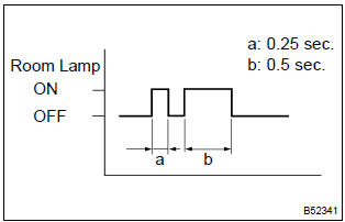
- Check that the system has switched to self–diagnostic mode by the blinking frequency of the room lamp.


6 Check by self–diagnostic mode
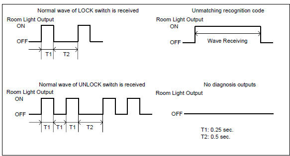
- Inspect the diagnosis outputs when the door control transmitter switch is held down (the diagnosis outputs can be checked with the outputs of the room lamp).
Hint
:
- in the case of a reception of the normal wave of the door lock and unlock switch (room lamp blinking), go to step a.
- In the case of an unmatching recognition code (room lamp on), go to step b.
- In the case of no diagnosis outputs (room lamp off), go to step c.

7 Register recognition code
- Check that the system can switch to rewrite mode or add mode and whether a recognition code can be registered.


Normal
8 Check response of door control receiver
- When a new or normal door control transmitter switch for the same type vehicle is held down, check that a diagnosis of unmatching recognition code is output.


Replace door control transmitter
9 Confirm input method of self–diagnostic mode
- When the method for switching the system to self–diagnostic mode works, proceed to a.
- when the method for switching the system to self–diagnostic mode does not work, proceed to b.


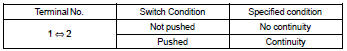
10 Inspect unlock warning switch assy
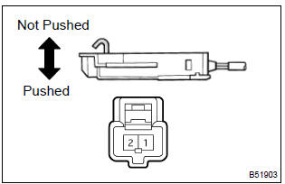
- Remove the key unlock warning switch.
- inspect the key unlock warning switch continuity, as shown in the illustration and table.
Standard:

11 Check wire harness (unlock warning switch @ instrument panel j/b and body ground)
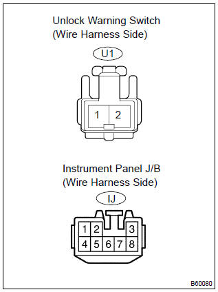
- Disconnect the unlock warning switch and instrument panel j/b connectors.
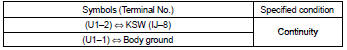
- check the continuity between the terminals of the unlock warning switch and instrument panel j/b connectors, as shown in the illustration and table.
Standard:

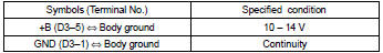
12 Check wire harness (door control receiver body ground)
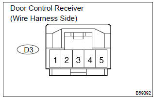
- Disconnect the connector from the door control receiver.
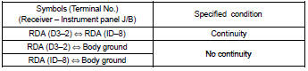
- check the voltage and continuity between the terminal of the door control receiver connector and the body ground, as shown in the illustration and table.
Standard:

13 Check door control receiver
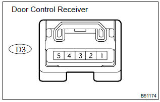
- Reconnect the connector to the door control receiver, and check the voltage between the terminal and the body ground, as shown in the illustration and table.
Standard:


14 Check wire harness (door control receiver instrument panel j/b) (door control receiver or instrument panel j/b body ground)
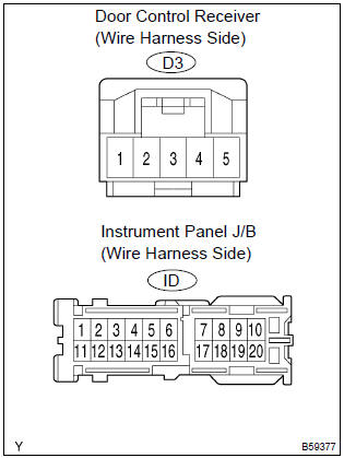
- Disconnect the door control receiver and instrument panel j/b connectors.
- check the continuity between the terminals of the door control receiver and instrument panel j/b connectors, as shown in the illustration and table.
Standard:

15 Replace door control receiver with normal one


Replace door control receiver
16 Replace integration relay with normal one

Replace integration relay


Other materials:
Inspection procedure
1 Inspect shift solenoid valve(sl)
Remove the shift solenoid valve sl.
measure the resistance according to the value(s) in the
table below.
Standard:
Connect the positive (+) battery lead to the solenoid connector
terminal, and the negative (–) battery lead to the
so ...
Circuit description
The throttle pressure that is applied to the primary regulator
valve (which modulates the line pressure) causes the solenoid
valve slt, under electronic control, to precisely and minutely
modulate and generate the line pressure according the extent
of the accelerator pedal depressed or the o ...
Basic repair hint
(A) hints on operations
1
Looks
Always wear a clean uniform.
Hat and safety shoes must be worn.
2
Vehicle protection
Set a grill cover, fender cover, seat cover and floor mat before
starting the operation.
3
Safe ...