
Toyota Corolla (E120) 2002–2008 Repair Manual / Diagnostics / Toyota vehicle intrusion protection system / Horn relay circuit / Inspection procedure
Toyota Corolla (E120): Inspection procedure
1 Check low pitched horn assy
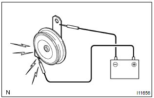
- Connect the positive (+) lead from the battery to the terminal and negative (–) lead to the horn body, and check that the horn blows.


2 Check relay (marking: horn)
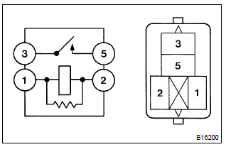
- Remove the relay from the engine room j/b.
- check the horn relay continuity, as shown in the illustration and table.
Standard:



3 Check wire harness (tvip ecu engine room j/b)
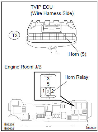
- Remove the horn relay from the engine room j/b.
- check the continuity between the terminals of the tvip ecu and engine room j/b connectors, as shown in the illustration and table.
Standard:

*: Horn relay terminal


4 Check wire harness (engine room j/b horn)
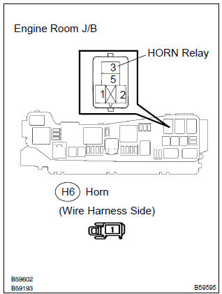
- Check the continuity between the terminals of the engine room j/b and horn connectors, as shown in the illustration and table.
Standard:

*: Horn relay terminal.


Check and replace tvip ecu


Other materials:
Circuit description
The vehicle speed sensor circuit is sent to cruise control ecu assy as a
vehicle speed signal. For each rotation
of the shaft, the vehicle speed sensor sends a signal through the combination
meter assembly to the
cruise control ecu assy (see the following chart). The cruise control ecu assy
...
Circuit description
Refer to dtc c0200/31, c0205/32, c1235/35, c1236/36
Hint:
Dtc no. C0210/33, c1238/38 is for the right rear speed sensor.
Dtc no. C0215/34, c1239/39 is for the left rear speed sensor.
Wiring diagram
...
Replacement
Hint:
installation is in the reverse order of the removal. But the
installation is indicated only when it has a
point.
In the lh side, work in the same procedure as in the rh side.
1. Disconnect battery negative terminal
2. Remove front seat assembly rh
3. Remove front seat inner be ...