Toyota Corolla (E120) 2002–2008 Repair Manual / Diagnostics / Supplemental restraint system / Short in squib (2nd step) circuit (to
b+) / Inspection procedure
Toyota Corolla (E120): Inspection procedure
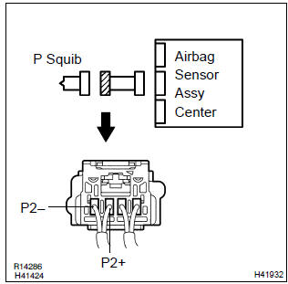
1 Check p squib circuit(airbag sensor assy center – instrument panel passenger airbag assy)
- Disconnect the negative (–) terminal cable from the battery, and wait at least for 90 seconds.
- disconnect the connector between the airbag sensor assy center and the instrument panel passenger airbag assy.
- connect the negative (–) terminal cable to the battery, and wait at least for 2 seconds.
- turn the ignition switch to on.
- for the connector (on the instrument panel passenger airbag assy side) between the airbag sensor assy center and the instrument panel passenger airbag assy, measure the voltage between p2+ and body ground.
Ok: voltage: below 1 v

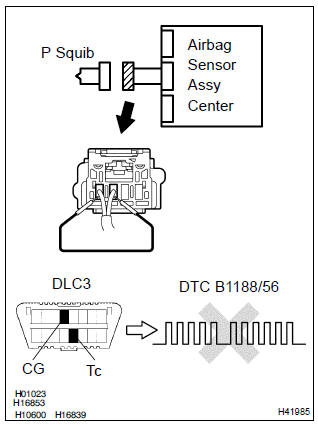
2 Check air bag sensor assy center
Sst 09843–18040
- Turn the ignition switch to lock.
- disconnect the negative (–) terminal cable from the battery, and wait at least for 90 seconds.
- connect the connector to the airbag sensor assy center.
- using a service wire, connect p2+ and p2– of the connector (on the instrument panel passenger airbag assy side) between the airbag sensor assy center and the instrument panel passenger airbag assy.
- connect the negative (–) terminal cable to the battery, and wait at least for 2 seconds.
- turn the ignition switch to on, and wait at least for 20 seconds.
- clear the dtc stored in memory .
- turn the ignition switch to lock, and wait at least for 20 seconds.
- turn the ignition switch to on, and wait at least for 20 seconds.
- check the dtc .
Ok: dtc b1188/56 is not output.
Hint
: codes other than code b1188/56 may be output at this time, but they are not relevant to this check.


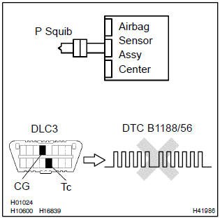
3 Check p squib
Sst 09843–18040
- Turn the ignition switch to lock.
- disconnect the negative (–) terminal cable from the battery, and wait at least for 90 seconds.
- connect the instrument panel passenger airbag assy connector.
- connect the negative (–) terminal cable to the battery, and wait at least for 2 seconds.
- turn the ignition switch to on, and wait at least for 20 seconds.
- clear the dtc stored in memory .
- turn the ignition switch to lock, and wait at least for 20 seconds.
- turn the ignition switch to on, and wait at least for 20 seconds.
- check the dtc .
Ok: dtc b1188/56 is not output.
Hint
: codes other than code b1188/56 may be output at this time, but they are not relevant to this check.

4 Use simulation method to check


Replace all srs components including the wire harness


Other materials:
Inspection procedure
Hint:
read freeze frame data using the hand–held tester or the obd ii scan tool.
Freeze frame data records the
engine conditions when a malfunction is detected. When troubleshooting, it is
useful for determining whether
the vehicle was running or stopped, the engine was warmed up or not, th ...
Inspection procedure
Hint:
start the inspection from step 1 in case of using the hand–held tester and start
from step 2 in case of not
using the hand–held tester.
1 Perform active test by hand–held tester(abs warning light)
Check that ”on” and ”off” of the abs warning light can be shown on the
...
Air conditioning controls
■ Adjusting the temperature setting
To adjust the temperature setting, turn
clockwise to increase the temperature
and turn counterclockwise to decrease
the temperature.
■ Fan speed setting
Press “>” on to increase the fan
speed.
Press “<” on to decrease the ...