Toyota Corolla (E120): Overhaul
Hint
: components:
1. Discharge refrigerant from refrigeration system
sst 07110–58060 (07117–58080, 07117–58090, 07117–78050, 07117–88060, 07117–88070, 07117–88080)
2. Disconnect cooler refrigerant liquid pipe a
- Remove the bolt and disconnect the cooler refrigerant liquid pipe a from the w/receiver condenser assy.
- remove the o–ring from the cooler refrigerant liquid pipe a.
Notice
: seal the opening of the disconnected parts using vinyl tape to prevent moisture and foreign matter from entering.
3. Disconnect discharge hose sub–assy
- Remove the bolt and discharge hose sub–assy from the w/receiver condenser assy.
- remove the o–ring from the discharge hose sub–assy.
Notice
: seal the opening of the disconnected parts using vinyl tape to prevent moisture and foreign matter from entering.
4. Remove w/receiver condenser assy
- Remove the 2 bolts and 2 radiator upper supports.
- Remove the 2 bolts.
- slide the upper part of the radiator assy rearward to remove the w/receiver condenser assy.
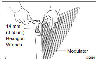
5. Remove cooler dryer
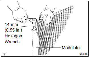
- Using a socket hexagon wrench 14 mm (0.55 In.), Remove the cap from the modulator.
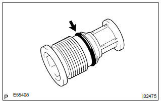
- Remove the o–ring from the cap.
- Using pliers, remove the cooler dryer.
6. Install cooler dryer
- using pliers, install the cooler dryer.
- Install the new o–ring to the cap.
- sufficiently apply compressor oil to the fit surfaces of the
o–ring and the cap.
Compressor oil: nd–oil 8 or equivalent
- Using a socket hexagon wrench 14 mm (0.55 In.), Install
the cap to the modulator.
Torque: 2.9 Nvm (29 kgfvcm, 25 in.Vlbf)
7. Install w/receiver condenser assy
- Install the w/receiver condenser assy with the 2 bolts.
Torque: 9.8 Nvm (100 kgfvcm, 87 in.Vlbf)
- Install the 2 radiator upper supports with the 2 bolts.
8. Install discharge hose sub–assy
- remove the attached vinyl tape from the hose and connecting part of the w/receiver condenser assy.
- sufficiently apple compressor oil to the new o–ring and
hose joint.
Compressor oil: nd–oil 8 or equivalent
- install a o–ring to the discharge hose sub–assy.
- Install the discharge hose sub–assy to the w/receiver
condenser assy with the bolt.
Torque: 5.4 Nvm (54 kgfvcm, 48 in.Vlbf)
9. Install cooler refrigerant liquid pipe a
- remove the attached vinyl tape from the pipe and w/receiver condenser assy.
- sufficiently apple compressor oil to the new o–ring and
pipe joint.
Compressor oil: nd–oil 8 or equivalent
- install a o–rings to the cooler refrigerant liquid pipe a.
- Install the cooler refrigerant liquid pipe a to the w/receiver
condenser assy with the bolt.
Torque: 5.4 Nvm (54 kgfvcm, 48 in.Vlbf)
10. Charge refrigerant
sst 07110–58060 (07117–58060, 07117–58070, 07117–58080, 07117–58090, 07117–78050, 07117–88060, 07117–88070, 07117–88080), 07117–48130, 07117–48140 specified amount: 490 30 g (17.28 1.06 Oz.)
11. Warm up engine
12. Inspect leakage of refrigerant


Other materials:
For safe driving
For safe driving, adjust the
seat and mirror to an appropriate
position before driving.
Correct driving posture
Adjust the angle of the seatback
so that you are sitting
straight up and so that you do
not have to lean forward to
steer.
Adjust the seat so that you
can depress the pedals fully ...
Replacement
Hint: components:
1. Precaution
2. Disconnect battery negative terminal
3. Remove air bag front rh sensor
Disconnect the connector from the airbag front rh sensor.
remove the 2 bolts and airbag front rh sensor.
4. Inspect air bag front rh sensor
5. Install air bag front rh ...
How to use this manual
General information
1. General description
This manual is made in accordance with sae j2008.
generally, repair operations can be separated in the following 3
main processes:
Diagnosis
Removing/installing, replacing, disassembling/reassembling,
checking and adju ...