Toyota Corolla (E120): Circuit description
The p squib (2nd step) circuit consists of the airbag sensor assy center and instrument panel passenger airbag assy.
It causes the srs to deploy when the srs deployment conditions are satisfied.
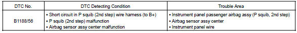
Dtc b1188/56 is recorded when a b+ short is detected in the p squib (2nd step) circuit.
Wiring diagram


Other materials:
Inspection procedure
1 Check side squib(lh) circuit(airbag sensor assy center – front
seat airbag assy lh)
Disconnect the negative (–) terminal cable from the battery,
and wait at least for 90 seconds.
disconnect the connectors between the airbag sensor
assy center and the front seat airbag assy ...
Ecm/pcm processor
Dtc p0606 ecm/pcm processor
Monitor description
The ecm continuously monitors its internal circuits. This self–check insures
that the ecm is functioning properly.
If a malfunction is detected, the ecm will set the appropriate dtc and
illuminate the mil.
The two cpus, main and sub cpu i ...
Alarm
The alarm uses light and
sound to give an alert when
an intrusion is detected.
The alarm is triggered in the
following situations when
the alarm is set:
A locked door or trunk is
unlocked or opened in any
way other than using the
entry function (if equipped),
wireless remote control,
mechani ...