Toyota Corolla (E120): Inspection procedure
1 Check p squib circuit(airbag sensor assy center – instrument panel passenger airbag assy)
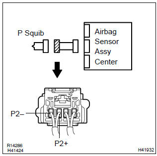
- Disconnect the negative (–) terminal cable from the battery, and wait at least for 90 seconds.
- disconnect the connector between the airbag sensor assy center and the instrument panel passenger airbag assy.
- for the connector (on the instrument panel passenger airbag
assy side) between the airbag sensor assy center
and the instrument panel passenger airbag assy, measure
the resistance between p2+ and body ground.
Ok: resistance: 1 mΩ or higher

2 Check air bag sensor assy center
Sst 09843–18040
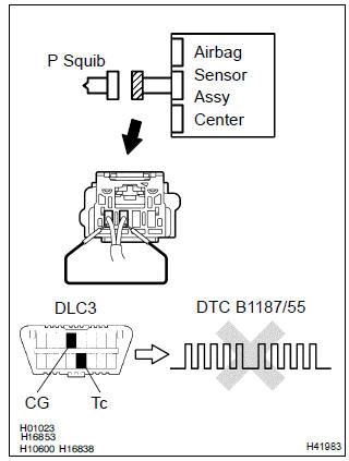
- Connect the connector to the airbag sensor assy center.
- using a service wire, connect p2+ and p2– of the connector (on the instrument panel passenger airbag assy side) between the airbag sensor assy center and the instrument panel passenger airbag assy.
- connect the negative (–) terminal cable to the battery, and wait at least for 2 seconds.
- turn the ignition switch to on, and wait at least for 20 seconds.
- clear the dtc stored in memory .
- turn the ignition switch to lock, and wait at least for 20 seconds.
- turn the ignition switch to on, and wait at least for 20 seconds.
- check the dtc .
Ok: dtc b1187/55 is not output.
Hint
: codes other than code b1187/55 may be output at this time, but they are not relevant to this check.


3 Check p squib
Sst 09843–18040
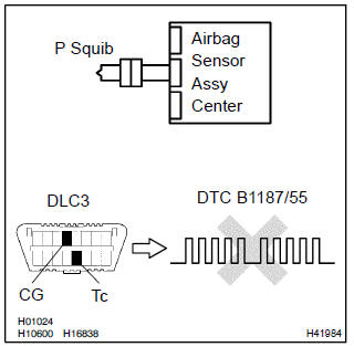
- Turn the ignition switch to lock.
- disconnect the negative (–) terminal cable from the battery, and wait at least for 90 seconds.
- connect the instrument panel passenger airbag assy connector.
- connect the negative (–) terminal cable to the battery, and wait at least for 2 seconds.
- turn the ignition switch to on, and wait at least for 20 seconds.
- clear the dtc stored in memory .
- turn the ignition switch to lock, and wait at least for 20 seconds.
- turn the ignition switch to on, and wait at least for 20 seconds.
- check the dtc .
Ok: dtc b1187/55 is not output.
Hint
: codes other than code b1187/55 may be output at this time, but they are not relevant to this check.

4 Use simulation method to check


Replace all srs components including the wire harness


Other materials:
Wiper & washer
Preparation
Sst
Recomended tools
Equipment
...
Monitor description
The battery supplies electricity to the ecm even when the ignition switch is
off. This electricity allows the
ecm store data such as dtc history, freeze frame data, fuel trim values, and
other data. If the battery voltage
falls below a minimum level, the ecm will conclude that there is a fault ...
Radio broadcast cannot be received (bad reception)
Inspection procedure
1 Check if radio auto–search functions properly
Check if the radio auto–search functions properly.
Perform the auto–search of the radio and check that it functions
normally.
Standard: the radio auto–search functions properly.
2 Check optional ...