Toyota Corolla (E120): Inspection procedure
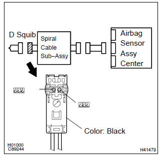
1 Check d squib circuit(airbag sensor assy center – horn button assy)
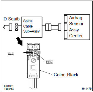
- Disconnect the negative (–) terminal cable from the battery, and wait at least for 90 seconds.
- disconnect the connector between the airbag sensor assy center and the horn button assy.
- for the black connector (on the spiral cable sub–assy
side) between the horn button assy and the spiral cable
sub–assy, measure the resistance between d2+ and
body ground.
Ok: resistance: 1 mw or higher


2 Check air bag sensor assy center
Sst 09843–18040
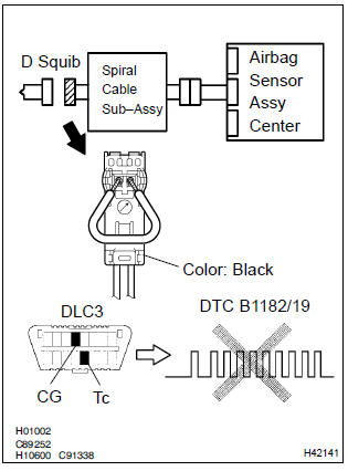
- Connect the connector to the airbag sensor assy center.
- using a service wire, connect d2+ and d2– of the black connector (on the spiral cable sub–assy side) between the horn button assy and the spiral cable sub–assy.
- connect the negative (–) terminal cable to the battery, and wait at least for 2 seconds.
- turn the ignition switch to on, and wait t least for 20 seconds.
- clear the dtc stored in memory .
- turn the ignition switch to lock, and wait at least for 20 seconds.
- turn the ignition switch to on, and wait at least for 20 seconds.
- check the dtc .
Ok: dtc b1182/19 is not output.
Hint
: codes other than code b1182/19 may be output at this time, but they are not relevant to this check.


3 Check d squib
Sst 09843–18040
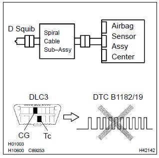
- Turn the ignition switch to lock.
- disconnect the negative (–) terminal cable from the battery, and wait at least for 90 seconds.
- connect the horn button assy connectors.
- connect the negative (–) terminal cable to the battery, and wait at least for 2 seconds.
- turn the ignition switch to on, and wait at least for 20 seconds.
- clear the dtc stored in memory .
- turn the ignition switch to lock, and wait at least for 20 seconds.
- turn the ignition switch to on, and wait at least for 20 seconds.
- check the dtc .
Ok: dtc b1182/19 is not output.
Hint
: codes other than code b1182/19 may be output at this time, but they are not relevant to this check.


4 Use simulation method to check


Replace all srs components including the wire harness
5 Check instrument panel wire(airbag sensor assy center – spiral cable sub–assy)
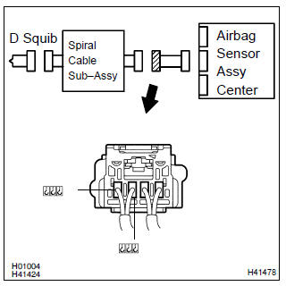
- Disconnect the connector of the instrument panel wire.
- for the connector (on the spiral cable sub–assy side) between
the airbag sensor assy center and the spiral cable
sub–assy, measure the resistance between d2+ and
body ground.
Ok: resistance: 1 mΩ or higher

6 Check spiral cable sub–assy
- For the black connector (on the spiral cable sub–assy
side) between the horn button assy and the spiral cable
sub–assy, measure the resistance between d2+ and
body ground.
Ok: resistance: 1 mΩ or higher


7 Use simulation method to check

Replace all srs components including the wire harness


Other materials:
Circuit description
Refer to dtc p0120
Dtc no.
Dtc detection condition
Trouble area
P0121
The following condition is met 4 times. After the vehicle speed
has exceeded 19 mph (30 km/h) once, the throttle position
sensor output value is out of normal range when the throttle
...
Playing audio CDs and MP3/WMA discs
CD player operation
Insert a disc or press to begin
listening to a disc.
1 Power
2 Volume
3 Eject a disc
4 Repeat play
5 Random playback 6 Select a track/file or display
track/folder list
7 Displays text message
8 Playback
9 Select a folder (MP3/WMA discs only), fast-forward or revers ...
Check mode procedure
Hint:
hand–held tester only:
compared to the normal mode, the check mode has more sensing
ability to detect malfunctions. Furthermore, the same diagnostic
items which are detected in the normal mode can also be
detected in the check mode.
1. Check mode procedure(using the hand–held tester) ...