Toyota Corolla (E120) 2002–2008 Repair Manual / Diagnostics / Supplemental restraint system / Open in d squib (2nd step) circuit / Inspection procedure
Toyota Corolla (E120): Inspection procedure
1 Check d squib circuit(airbag sensor assy center – horn button assy)
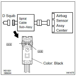
- Disconnect the negative (–) terminal cable from the battery, and wait at least for 90 seconds.
- disconnect the connectors between the horn button assy and the airbag sensor assy center.
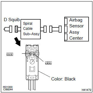
- for the black connector (on the spiral cable sub–assy
side) between the horn button assy and the spiral cable
sub–assy, measure the resistance between d2+ and
d2–.
Ok: resistance: below 1 Ω


2 Check air bag sensor assy center
Sst 09843–18040
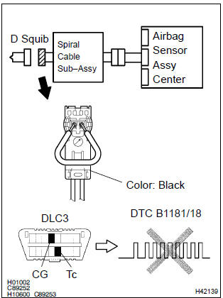
- Connect the connector to the airbag sensor assy center.
- using a service wire, connect d2+ and d2– of the black connector (on the spiral cable sub–assy side) between the horn button assy and the spiral cable sub–assy.
- connect the negative (–) terminal cable to the battery, and wait at least for 2 seconds.
- turn the ignition switch to on, and wait at least for 20 seconds.
- clear the dtc stored in memory .
- turn the ignition switch to lock, and wait at least for 20 seconds.
- turn the ignition switch to on, and wait at least for 20 seconds.
- check the dtc .
Ok: dtc b1181/18 is not output.
Hint
: codes other than code b1181/18 may be output at this time, but they are not relevant to this check.


3 Check d squib
Sst 09843–18040
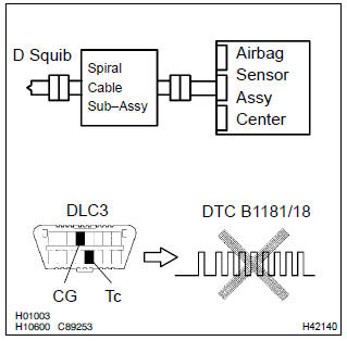
- Turn the ignition switch to lock.
- disconnect the negative (–) terminal cable from the battery, and wait at least for 90 seconds.
- connect the horn button assy connectors.
- connect the negative (–) terminal cable to the battery, and wait at least for 2 seconds.
- turn the ignition switch to on, and wait at least for 20 seconds.
- clear the dtc stored in memory .
- turn the ignition switch to lock, and wait at least for 20 seconds.
- turn the ignition switch to on, and wait at least for 20 seconds.
- check the dtc .
Ok: dtc b1181/18 is not output.
Hint
: codes other than code b1181/18 may be output at this time, but they are not relevant to this check.


Use simulation method to check
4 Check instrument panel wire(airbag sensor assy center – spiral cable sub–assy)
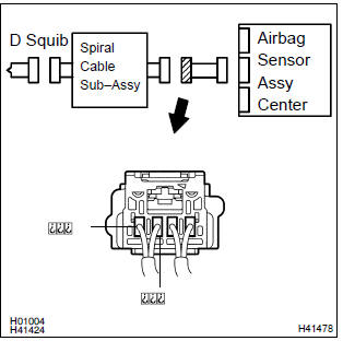
- Disconnect the connector of the instrument panel wire.
- for the connector (on the spiral cable sub–assy side) between
the airbag sensor assy center and the spiral cable
sub–assy, measure the resistance between d2+ and
d2–.
Ok: resistance: below 1 w

5 Check spiral cable sub–assy
- For the black connector (on the spiral cable sub–assy
side) between the horn button assy and the spiral cable
sub–assy, measure the resistance between d2+ and
d2–.
Ok: resistance: below 1 Ω


Use simulation method to check


Other materials:
Circuit description
The o/d main switch (transmission control switch) is a momentary type switch.
When pressing the o/d main
switch, the o/d off indicator light lights up and the ecm prohibits shifting
into o/d, and when pressing it
once again, the o/d off indicator light goes off and the ecm allows shifting
in ...
Deleting call histories
Select “Delete Call History” using
. ● Deleting outgoing call history
1 Select “Outgoing Calls” using .
2 Select the desired phone number using
and press
(YES).
To delete all outgoing call history data, press
(ALL) and then press
(YES).
● Deleting incoming call histo ...
Circuit description
The speed sensor detects wheel speed and transmits the appropriate
signals to the ecu. These signals are used for control
of the abs control system. Each of the front and rear rotors has
48 serrations.
When the rotors rotate, the magnetic field generated by the permanent
magnet in the spe ...