Toyota Corolla (E120) 2002–2008 Repair Manual / Diagnostics / Sfi system / System voltage / Inspection procedure
Toyota Corolla (E120): Inspection procedure
Hint
: read freeze frame data using the hand-held tester or the obd ii scan tool. Freeze frame data records the engine conditions when a malfunction is detected. When troubleshooting, it is useful for determining whether the vehicle was running or stopped, the engine was warmed up or not, the air–fuel ratio was lean or rich, etc. At the time of the malfunction.
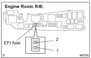
1 Check fuse(efi fuse)
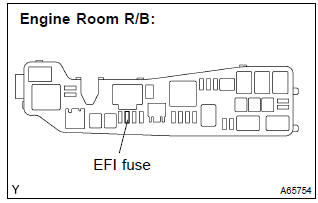
- Remove the efi fuse from the engine room r/b.
- check for continuity in the efi fuse.
Standard: continuity
- reinstall the efi fuse.

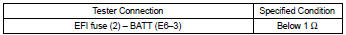
2 Inspect ecm(batt voltage)
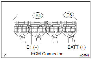
- Measure the voltage between the terminals of the e4 and e6 ecm connectors.
Standard:


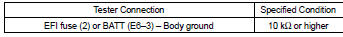
3 Check harness and connector(ecm – efi fuse, efi fuse – battery)
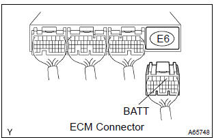
- Check the harness and the connector between the efi fuse and ecm.
- Remove the efi fuse from the engine room r/b.
- Disconnect the e6 ecm connector.
- Check the resistance between the wire harness side connectors.
Standard (check for open):
Standard (check for short):
- Reconnect the ecm connector.
- Reinstall the efi fuse.
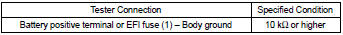
- check the harness and the connector between the efi fuse and battery.
- Remove the efi fuse from the engine room r/b.
- Disconnect the battery positive terminal.
- Check the resistance between the wire harness side connectors.
Standard (check for open):

Standard (check for short):
- Reconnect the battery positive terminal.
- Reinstall the efi fuse.

Check and replace engine room relay block assy


Other materials:
Overhaul
1. Inspect 1st gear thrust clearance
Using a feeler gauge, measure the 1st gear thrust clearance.
Standard clearance:
0.10 – 0.40 Mm (0.0039 – 0.0157 In.)
2. Inspect 2nd gear thrust clearance
Using a dial indicator, measure the 2nd gear thrust clearance.
Standard clearan ...
Inspection procedure
Hint:
if dtcs p0115, p0116, p0117, p0118 and p0125 are output
simultaneously, the engine coolant temperature
sensor circuit may be open or short. Perform the troubleshooting of dtc
p0115, p0117 or
p0118 first.
Read freeze frame data using the hand-held tester or the obd ii scan
to ...
Customization
Customizable features
Your vehicle includes a variety
of electronic features
that can be personalized to
suit your preferences. The
settings of these features
can be changed using the
multi-information display,
the audio system screen, or
at your Toyota dealer.
Customizing vehicle features
■ Chang ...