Toyota Corolla (E120) 2002–2008 Repair Manual / Diagnostics / Sfi system / Engine coolant temperature circuit / Circuit description
Toyota Corolla (E120): Circuit description
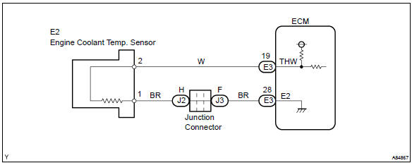
A thermistor is built in the engine coolant temperature sensor and changes the resistance value according to the engine coolant temperature.
The structure of the sensor and connection to the ecm is the same as those of the intake air temperature sensor.
Hint
: if the ecm detects the dtc p0115, p0117 or p0118, it operates the fail–safe function in which the engine coolant temperature is assumed to be 80 c (176 °F).
|
Dtc no. |
Proceed to |
Dtc detection condition |
Trouble area |
| P0115 | Step 1 | Open or short in engine coolant temperature sensor circuit for 0.5 Seconds |
|
| P0117 | Step 4 | Short in engine coolant temperature sensor circuit for 0.5 Seconds | |
| P0118 | Step 2 | Open in engine coolant temperature sensor circuit for 0.5 Seconds |
Hint
: after confirming dtc p0115, p0117 or p0118, confirm the engine coolant temperature in the ”diagnosis/ enhanced obd ii/data list/all” using the hand–held tester or the obd ii scan tool.

Monitor description
The engine coolant temperature (ect) sensor is used to monitor the engine coolant temperature. The ect sensor has a thermistor that varies its resistance depending on the temperature of the engine coolant. When the coolant temperature is low, the resistance in the thermistor increases. When the temperature is high, the resistance drops. The variations in resistance are reflected in the voltage output from the sensor. The ecm monitors the sensor voltage and uses this value to calculate the engine coolant temperature. When the sensor output voltage deviates from the normal operating range, the ecm interprets this as a fault in the ect sensor and sets a dtc.
Example: when the ecm calculates that the ect is –40 c (–40 °F), or more than 140 c (284 °F), and if either the condition continues for 0.5 Sec or more, the ecm will set a dtc.
Monitor strategy
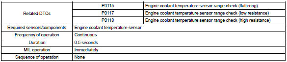
Typical enabling conditions

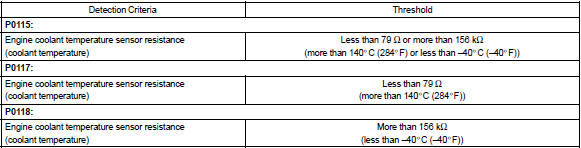
Typical malfunction thresholds
Component operating range

Wiring diagram


Other materials:
SRS airbags
The SRS airbags inflate when the vehicle is subjected to certain types of
severe impacts that may cause significant injury to the occupants. They work together
with the seat belts to help reduce the risk of death or serious injury.
◆ SRS front airbags
1 SRS driver airbag/front passenge ...
Overhaul
Caution:
wear the gloves, because the cutting surface of the seat back frame and seat
adjuster may injure
your hand.
Hint:
tape the screwdriver tip before use when prying parts.
1. Disconnect battery negative terminal
Caution:
wait for 90 seconds after disconnecting the battery terminal a ...
Under hood
General maintenance
1. General notes
maintenance requirements vary depending on the country.
Check the maintenance schedule in the owner’s manual supplement.
Following the maintenance schedule is mandatory.
Determine the appropriate time to service the vehicle using either miles
driv ...