Toyota Corolla (E120): Inspection procedure
1 Check side squib(lh) circuit(airbag sensor assy center – front seat airbag assy lh)
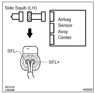
- Disconnect the negative (–) terminal cable from the battery, and wait at least for 90 seconds.
- disconnect the connectors between the airbag sensor assy center and the front seat airbag assy (lh).
- for the connector (on the front seat airbag assy side) between
the airbag sensor assy center and the front seat
airbag assy (lh), measure the resistance between sfl+
and body ground.
Ok: resistance: 1 mw or higher

2 Check air bag sensor assy center
Sst 09843–18040
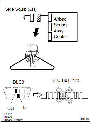
- Connect the connector to the airbag sensor assy center.
- using a service wire, connect sfl+ and sfl– of the connector (on the front seat airbag assy side) between the airbag sensor assy center and the front seat airbag assy (lh).
- connect the negative (–) terminal cable to the battery, and wait at least for 2 seconds.
- turn the ignition switch to on, and wait at least for 20 seconds.
- clear the dtc stored in memory .
- turn the ignition switch to lock, and wait at least for 20 seconds.
- turn the ignition switch to on, and wait at least for 20 seconds.
- check the dtc .
Ok: dtc b0117/45 is not output.
Hint
: codes other than code b0117/45 may be output at this time, but they are not relevant to this check.


3 Check side squib(lh)
Sst 09843–18040
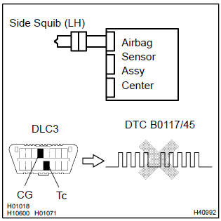
- Turn the ignition switch to lock.
- disconnect the negative (–) terminal cable from the battery, and wait at least for 90 seconds.
- connect the front front seat airbag assy (lh) connector.
- connect the negative (–) terminal cable to the battery, and wait at least for 2 seconds.
- turn the ignition switch to on, and wait at least for 20 seconds.
- clear the dtc stored in memory .
- turn the ignition switch to lock, and wait at least for 20 seconds.
- turn the ignition switch to on, and wait at least for 20 seconds.
- check the dtc .
Ok: dtc b0117/45 is not output.
Hint
: codes other than code b0117/45 may be output at this time, but they are not relevant to this check.

4 Use simulation method to check


Replace all srs components including the wire harness


Other materials:
Front passenger occupant classification system
Your vehicle is equipped with a front passenger occupant classification system.
This system detects the conditions of the front passenger seat and activates or
deactivates the devices for the front passenger.
1 SRS warning light
2 Seat belt reminder light
3 “AIR BAG OFF” indicator light ...
On–vehicle inspection
1. Check cooling fan operation with low temperature (below 83 c (181 f))
Turn the ignition switch on.
check that the cooling fan stops.
Hint:
if not, check the cooling fan relay and water temperature sensor, and check for
separated connector or severed
wire between the cooling fan ...
Precaution
1. Check that the battery cables are connected to the correct terminals.
2. Disconnect the battery cables when the battery is given a quick charge.
3. Do not perform tests with a high voltage insulation resistance tester.
4. Never disconnect the battery while the engine is running.
5. Check that ...