Toyota Corolla (E120) 2002–2008 Repair Manual / Diagnostics / Supplemental restraint system / Open in d squib circuit / Inspection procedure
Toyota Corolla (E120): Inspection procedure
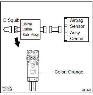
1 Check d squib circuit(airbag sensor assy center – horn button assy)
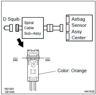
- Disconnect the negative (–) terminal cable from the battery, and wait at least for 90 seconds.
- disconnect the connectors between the horn button assy and the airbag sensor assy center.
- for the orange connector (on the spiral cable sub–assy
side) between the horn button assy and the spiral cable
sub–assy, measure the resistance between d+ and d–.
Ok: resistance: below 1 Ω


2 Check air bag sensor assy center
Sst 09843–18040
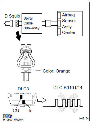
- Connect the connector to the airbag sensor assy center.
- using a service wire, connect d+ and d– of the orange connector (on the spiral cable sub–assy side) between the horn button assy and the spiral cable sub–assy.
- connect the negative (–) terminal cable to the battery, and wait at least for 2 seconds.
- turn the ignition switch to on, and wait at least for 20 seconds.
- clear the dtc stored in memory .
- turn the ignition switch to lock, and wait at least for 20 seconds.
- turn the ignition switch to on, and wait at least for 20 seconds.
- check the dtc .
Ok: dtc b0101/14 is not output.
Hint
: codes other than code b0101/14 may be output at this time, but they are not relevant to this check.


3 Check d squib
Sst 09843–18040
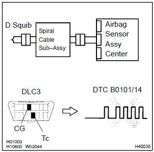
- Turn the ignition switch to lock.
- disconnect the negative (–) terminal cable from the battery, and wait at least for 90 seconds.
- connect the horn button assy connector.
- connect the negative (–) terminal cable to the battery, and wait at least for 2 seconds.
- turn the ignition switch to on, and wait at least for 20 seconds.
- clear the dtc stored in memory .
- turn the ignition switch to lock, and wait at least for 20 seconds.
- turn the ignition switch to on, and wait at least for 20 seconds.
- check the dtc .
Ok: dtc b0101/14 is not output.
Hint
: codes other than code b0101/14 may be output at this time, but they are not relevant to this check.


Use simulation method to c
4 Check instrument panel wire(airbag sensor assy center – spiral cable sub–assy)
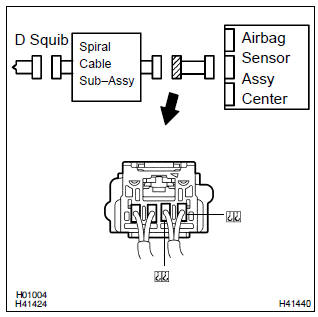
- Disconnect the connector of the instrument panel wire.
- for the connector (on the spiral cable sub–assy side) between
the airbag sensor assy center and the spiral cable
sub–assy, measure the resistance between d+ and d–.
Ok: resistance: below 1 Ω

5 Check spiral cable sub–assy
- For the orange connector (on the spiral cable sub–assy
side) between the horn button assy and the spiral cable
sub–assy, measure the resistance between d+ and d–.
Ok: resistance: below 1 Ω


Use simulation method to check


Other materials:
Engine hood/door
Preparation
Sst
Recomended tools
Equipment
...
Mass or volume air flow circuit
Dtc p0100 mass or volume air flow circuit
Dtc p0102 mass or volume air flow circuit
low input
Dtc p0103 mass or volume air flow circuit
high input
Circuit description
The maf (mass air flow) sensor measures the amount of air flowing through the
throttle valve. The ecm
uses this information ...
Radio broadcast cannot be received (bad reception)
Inspection procedure
1 Check if radio auto–search functions properly
Check if the radio auto–search functions properly.
Perform the auto–search of the radio and check that it functions
normally.
Standard: the radio auto–search functions properly.
2 Check optional ...