Toyota Corolla (E120): Replacement
1. Work for preventing gasoline from spilling out
2. Remove cylinder head cover no.2
- Remove the 2 nuts, 2 clips and cylinder head cover.
3. Disconnect ventilation hose
- Disconnect the ventilation hose from the cylinder head cover.
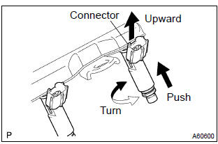
4. Disconnect engine wire
- Disconnect the 4 fuel injector connectors.
- remove the 3 wire harness clamps from the clamp brackets.
5. Remove efi fuel pipe clamp
- Remove the efi fuel pipe clamp.
6. Disconnect fuel tube sub–assy
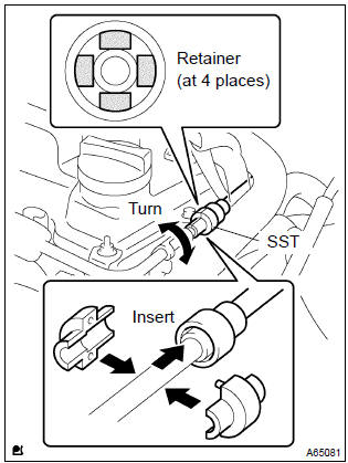
- Using a sst, disconnect the fuel tube.
Sst 09268–21010
- assemble the sst to the connection as shown.
- Turn the sst, align the retainers inside the connector with the sst chamfered parts and insert the sst into the connector.
- Slide the sst and the connector together towards the fuel tube assembly.
Notice
:
- check if there is dirt mud on the pipe and around the connector before disconnecting them and clean the dirt away.
- Do not bent, fold and rotate the nylon tube.
- When the connector and the pipe are stuck, push and pull the connector to free to disconnect and pull it out.
- Prevent the disconnected pipe and connector from damaging and mixing foreign objects by covering them with a vinyl bag.
7. Remove fuel delivery pipe sub–assy
- Remove the 3 bolts and fuel delivery pipe together with the 4 fuel injectors.
Notice
: be careful not to drop the fuel injectors when removing the fuel delivery pipe.
- Remove the 2 spacers from the cylinder head.
8. Remove fuel injector assy
- Pull out the 4 fuel injectors from the fuel delivery pipe.
9. Install fuel injector assy
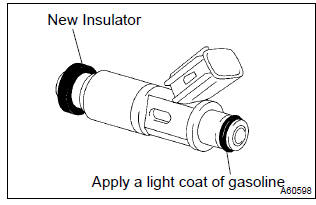
- Install a new insulator to the each fuel injector.
- apply a light coat of spindle oil or gasoline to a new o– ring, and install it to the each fuel injector.
Notice
: never use engine, gear or brake oil.
- Apply a light coat of spindle oil or gasoline on the place where the fuel delivery pipe touches on the o–ring.
- while turning the fuel injector clockwise and counterclockwise, and push it to the fuel delivery pipe.
Notice
:
- be careful not twist the o–ring.
- After installing the fuel injectors, check that they turns smoothly. If the fuel injector does not, reinstall it with a new o–ring.
10. Install fuel delivery pipe sub–assy
- Install the 2 spacers to the cylinder head.
- install the fuel delivery pipe together with the 4 fuel injectors
with the 3 bolts.
Torque:
bolt a 19 nvm (194 kgfvcm, 14 ftvlbf) bolt b 9.0 Nvm (92 kgfvcm, 80 in.Vlbf)
Notice
:
- be careful not drop the fuel injectors when installing the fuel delivery pipe.
- Check that the fuel injectors rotate smoothly after installing the fuel delivery pipe.
11. Connect fuel tube sub–assy
- Connect the fuel tube to the fuel delivery pipe.
Notice
:
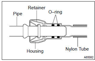
- check if there is any damage or foreign objects on the connected part of the fuel tube.
- After connecting, check if the fuel tube and the connector are securely connected by pulling them.
12. Install cylinder head cover no.2
- Install the cylinder head cover with the 2 nuts and 2 clips.
Torque: 7.0 Nvm (71 kgfvcm, 62 in.Vlbf)
13. Check fuel leak


Other materials:
Inspection procedure
1 Inspect parking brake switch circuit
Check for open and short circuit in parking brake switch circuit
2 Inspect brake fluid level warning switch circuit
Check the brake fluid level in reservoir.
check for open and shot circuit in brake fluid level warning
switch circuit
...
Front seat airbag assy rh
Disposal
Hint:
when scrapping vehicles equipped with an srs or disposing of the
front seat airbag assy always first
deploy the airbag in accordance with the procedure described below. If any
abnormality occurs with
the airbag deployment, contact the service dept. Of toyota motor sales ...
Hood
Adjustment
Hint:
since the centering bolt is used as a hood hinge and hood lock
set bolt, the hood and hood lock can not be adjusted with it on.
Substitute a bolt with washer for the centering bolt.
1. Inspect hood sub–assy
Check that the clearance is within the standard value.
...