Toyota Corolla (E120) 2002–2008 Repair Manual / Diagnostics / Sfi system / Fuel pump control circuit / Inspection procedure
Toyota Corolla (E120): Inspection procedure
Hand–held tester:
1 Perform active test by hand–held tester(operation of circuit opening relay)
- Connect the hand–held tester to the dlc3.
- turn the ignition switch on and push the hand–held tester main switch on.
- select the item ”diagnosis / enhanced obd ii / active test / fuel pump / spd”.
- check the relay operation while operating it with the hand–held tester.
Standard: operating noise can be heard from the relay.


2 Inspect ecm power source circuit

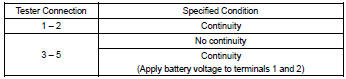
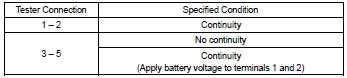
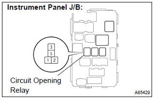
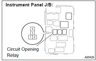
3 Inspect circuit opening relay
- Remove the circuit opening relay from the instrument panel j/b.
- check for continuity in the circuit opening relay.
Standard:
- Reinstall the circuit opening relay.


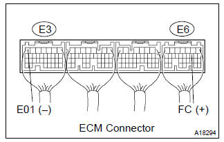
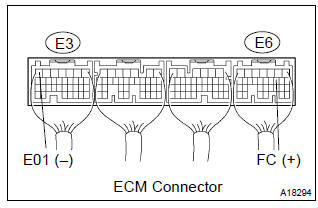
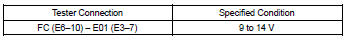
4 Inspect ecm(fc voltage)
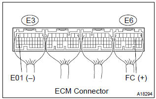
- Turn the ignition switch on.
- measure the voltage between the terminals of the e3 and e6 ecm connectors.
Standard:


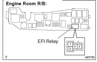
5 Check harness and connector(efi relay – circuit opening relay)
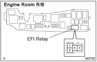
- Remove the efi relay from the engine room r/b.
- remove the circuit opening relay from the instrument panel j/b.
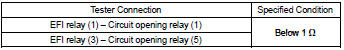
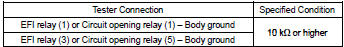
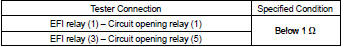
- check the resistance between the wire harness side connectors.
Standard (check for open):
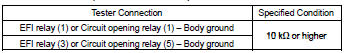
Standard (check for short):

- Reinstall the circuit opening relay.
- reinstall the efi relay.

Replace ecm
6 Inspect fuel pump

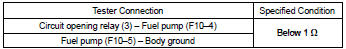
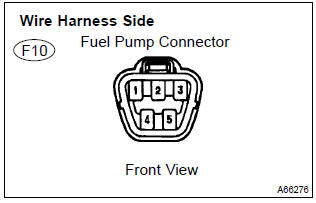
7 Check harness and connector(circuit opening relay – fuel pump, fuel pump – body ground)
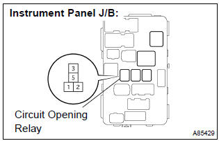
- Remove the circuit opening relay from the instrument panel j/b.
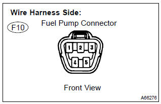
- disconnect the f10 fuel pump connector.
- check the resistance between the wire harness side connectors.
Standard (check for open):

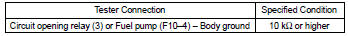
Standard (check for short):

- Reconnect the fuel pump connector.
- reinstall the circuit opening relay.

Replace ecm
Obd ii scan tool (excluding hand–held tester):
1 Check operation of fuel pump
- Turn the ignition switch on.
- connect between terminals fc and e01 of the ecm connector.
- check for fuel pressure in the fuel inlet hose when it is
pinched off.
Result: there is pressure in fuel inlet hose.
Hint
: at this time, you will hear the fuel flowing sound.

2 Inspect ecm power source circuit

3 Inspect circuit opening relay
- Remove the circuit opening relay from the instrument panel j/b.
- check for continuity in the circuit opening relay.
Standard:
- Reinstall the circuit opening relay.


4 Inspect ecm(fc voltage)
- Turn the ignition switch on.
- measure the voltage between the terminals of the e3 and e6 ecm connectors.
Standard:


5 Check harness and connector(efi relay – circuit opening relay)
- Remove the efi relay from the engine room r/b.
- remove the circuit opening relay from the instrument panel j/b.
- check the resistance between the wire harness side connectors.
Standard (check for open):
Standard (check for short):
- Reinstall the circuit opening relay.
- reinstall the efi relay.

Replace ecm
6 Inspect fuel pump


7 Check harness and connector(circuit opening relay – fuel pump,fuel pump – body ground)
- Remove the circuit opening relay from the instrument panel j/b.
- disconnect the f10 fuel pump connector.
- check the resistance between the wire harness side connectors.
Standard (check for open):
Standard (check for short):
- Reconnect the fuel pump connector.
- reinstall the circuit opening relay.

Replace ecm


Other materials:
Engine
On–vehicle inspection
Hint:
inspect these items on a cooled down engine.
1. Inspect drive belt
2. Replace spark plugs
3. Inspect air filter
Remove the air filter.
visually check that the air filter is not excessively damaged,
dirty or oily.
Peplace the air filter if nece ...
Parking the vehicle
► Automatic transmission or continuously
variable transmission Automatic transmission or continuously variable transmission
1 With the shift lever in D, depress the brake pedal.
2 Shift the shift lever to P.
3 Set the parking brake.
4 Vehicles without a smart key system: Turn ...
Inspection procedure
1 Check source voltage
Measure the voltage of the battery.
Ok:
voltage: 10 – 14 v
2 Check air bag sensor assy center
Disconnect the negative (–) terminal cable from the battery, and wait at
least for 90 seconds.
disconnect the connectors from the airbag sensor assy ...