Toyota Corolla (E120) 2002–2008 Repair Manual / Diagnostics / Sfi system / Fuel pump control circuit / Circuit description
Toyota Corolla (E120): Circuit description
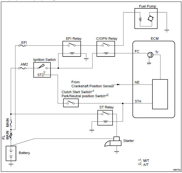
In the diagram below, when the engine is cranked, current flows from terminal st2 of the ignition switch to the starter relay coil and also current flows to terminal sta of the ecm (sta signal).
When the sta signal and ne signal are input to the ecm, tr is turned on, current flows to the coil of the circuit opening relay, the relay switches on, power is supplied to the fuel pump and the fuel pump operates.
While the ne signal is generated (engine running), the ecm keeps tr on (circuit opening relay on) and the fuel pump also keeps operating.
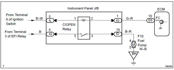
Wiring diagram


Other materials:
Inspection procedure
1 Input signal check
See the input signal check on page 05–745.
check the indicator light when the clutch pedal is depressed.
Ok:
the indicator light goes off when the clutch pedal is
depressed.
2 Inspect terminal voltage(d)
Turn the ignition switch to on.
&n ...
On–vehicle inspection
1. Inspect for electrical door lock operation
Hint:
w/ power window:
the door control switch is built in the master switch in the driver’s door
and also in the passenger’s
door.
W/o power window:
the door control switch is in the driver’s door and also in the passenger’s
d ...
Safety Connect
*: If equipped
Safety Connect is a subscription-
based telematics
service that uses Global
Positioning System (GPS)
data and embedded cellular
technology to provide
safety and security features
to subscribers. Safety Connect
is supported by Toyota's
designated response
center, which operates 24
hour ...