Toyota Corolla (E120) 2002–2008 Repair Manual / Diagnostics / Sfi system / Intake air temperature circuit / Inspection procedure
Toyota Corolla (E120): Inspection procedure
Hint
:
- if different dtcs related to different systems that have terminal e2 as the ground terminal are output simultaneously, terminal e2 may be open.
- Read freeze frame data using the hand-held tester or the obd ii scan tool. Freeze frame data records the engine conditions when a malfunction is detected. When troubleshooting, it is useful for determining whether the vehicle was running or stopped, the engine was warmed up or not, the air–fuel ratio was lean or rich, etc. At the time of the malfunction.
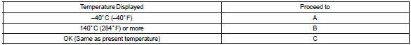
1 Read value of hand–held tester or obd ii scan tool(intake air temperature)
- Connect the hand–held tester or the obd ii scan tool to the dlc3.
- turn the ignition switch on and push the hand–held tester or the obd ii scan tool main switch on.
- select the item ”diagnosis / enhanced obd ii / data list / all / intake air” and read its value displayed on the hand–held tester or the obd ii scan tool.
Temperature: same value as the actual intake air temperature.
Result:
Hint
:
- if there is an open circuit, the hand–held tester or the obd ii scan tool indicates –40 °C (–40°f).
- If there is a short circuit, the hand–held tester or the obd ii scan tool indicates 140 °C (284°f) or more.

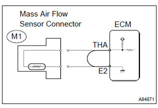
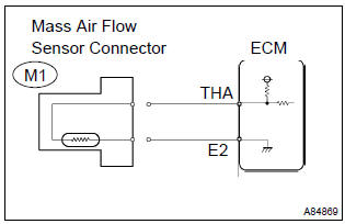
2 Read value of hand–held tester or obd ii scan tool(check for open in wire harness)
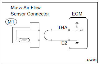
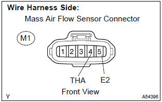
- Disconnect the m1 mass air flow sensor connector
- connect terminals tha and e2 of the mass air flow sensor wire harness side connector.
- turn the ignition switch on.
- select the item ”diagnosis / enhanced obd ii /
data list / all / intake air” and read its value displayed
on the hand–held tester or the obd ii scan tool.
Temperature value: 140 °C (284°f) or more
- reconnect the mass air flow sensor connector.

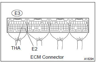
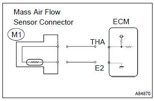
3 Read value of hand–held tester or obd ii scan tool(check for open in ecm)
- Disconnect the m1 mass air flow sensor connector.
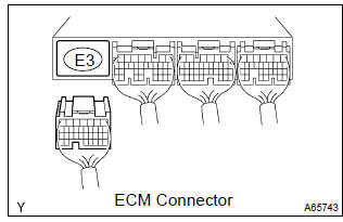
- connect the terminals tha and e2 of the e3 ecm connector.
Hint
: before checking, do a visual and contact pressure check on the ecm connector.
- turn the ignition switch on.
- select the item ”diagnosis / enhanced obd ii /
data list / all / intake air” and read its value displayed
on the hand–held tester or the obd ii scan tool.
Temperature value: 140 °C (284°f) or more
- reconnect the mass air flow sensor connector.

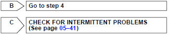
Confirm good connection at ecm. If ok, replace ecm
4 Read value of hand–held tester or obd ii scan tool(check for short in wire harness)
- Disconnect the m1 mass air flow sensor connector.
- turn the ignition switch on.
- select the item ”diagnosis / enhanced obd ii /
data list / all / intake air” and read its value displayed
on the hand–held tester or the obd ii scan tool.
Temperature value: –40 °C (–40°f)
- reconnect the mass air flow sensor connector.


5 Read value of hand–held tester or obd ii scan tool(check for short in ecm)
- Disconnect the e3 ecm connector.
- turn the ignition switch on.
- select the item ”diagnosis / enhanced obd ii /
data list / all / intake air” and read its value displayed
on the hand–held tester or the obd ii scan tool.
Temperature value: –40 °C (–40°f)
- reconnect the ecm connector.

Replace ecm


Other materials:
Windshield wiper motor assy
Replacement
1. Remove windshield wiper arm cover
2. Remove fr wiper arm rh
operate the wiper and stop the windshield wiper motor assy at the
automatic stop position.
remove a nut and fr wiper arm rh.
3. Remove fr wiper arm lh
remove a nut and fr wiper arm lh.
4 ...
Safety information for children
Observe the following precautions when children are in the vehicle.
Use a child restraint system appropriate for the child, until the child becomes
large enough to properly wear the vehicle’s seat belt.
● It is recommended that children sit in the rear seats to avoid accidental contact
...
Engine assembly
Inspection
1. Inspect coolant
2. Inspect engine oil
3. Inspect battery
4. Inspect air cleaner filter element sub–assy
5. Inspect spark plug
6. Inspect fan and generator v belt
Hint:
you don’t need to check the belt deflection because auto tensioner is adopted.
7. Inspect ignition ti ...