Toyota Corolla (E120) 2002–2008 Repair Manual / Diagnostics / Sfi system / Intake air temperature circuit / Circuit description
Toyota Corolla (E120): Circuit description
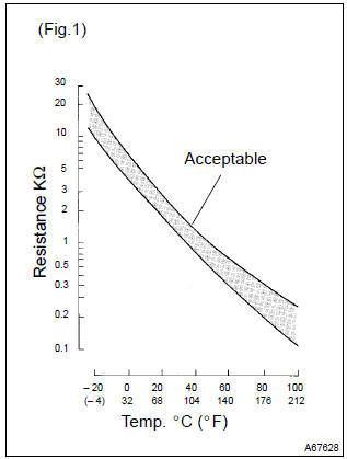
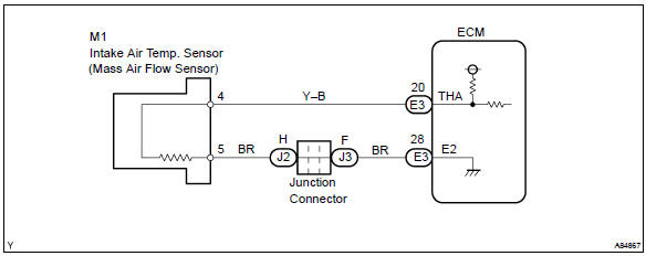
The intake air temperature (iat) sensor, mounted on the mass air flow (maf) sensor, monitors the intake air temperature. The iat sensor has a thermistor that varies its resistance depending on the temperature of the intake air. When the air temperature is low, the resistance in the thermistor increases. When the temperature is high, the resistance drops. The variations in resistance are reflected as voltage changes to the ecm terminal.
(See fig. 1).
The intake air temperature sensor is connected to the ecm.
The 5 v power source voltage in the ecm is applied to the intake air temperature sensor from terminal tha (thar) via resistor r.
That is, the resistor r and the intake air temperature sensor are connected in series. When the resistance value of the intake air temperature sensor changes in accordance with changes in the intake air temperature, the potential at terminal tha (thar) also changes. Based on this signal, the ecm increases the fuel injection volume to improve the drive ability during cold engine operation.
|
Dtc no. |
Proceed to |
Dtc detection condition |
Trouble area |
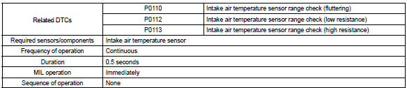
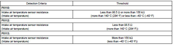
| P0110 | Step 1 | Open or short in intake air temperature sensor circuit for 0.5 Seconds |
|
| P0112 | Step 4 | Short in intake air temperature sensor circuit for 0.5 Seconds | |
| P0113 | Step 2 | Open in intake air temperature sensor circuit for 0.5 Seconds |
Hint
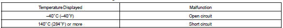
: after confirming dtc p0110, p0112 or p0113, confirm the intake air temperature in the ”diagnosis / enhanced obd ii / data list / all” using the hand–held tester or the obd ii scan tool.
Monitor description
The ecm monitors the sensor voltage and uses this value to calculate the intake air temperature. When the sensor output voltage deviates from the normal operating range, the ecm interprets this as a fault in the iat sensor and sets a dtc.
Example: when the sensor voltage output equal to –40 c (–40 °F) or more than 140 c (284 °F).
Monitor strategy
Typical enabling conditions

Typical malfunction thresholds
Component operating range

Wiring diagram


Other materials:
On–vehicle inspection
1. Inspect drive belt
Visually check the belt for excessive wear, frayed cords,
etc.
If any defect is found, replace the drive belt.
Hint:
cracks on the rib side of a belt are considered acceptable. If the
missing chunks from the ribs are found on the belt, it should be
replaced.
2 ...
Inspection procedure
1 Inspect transmission wire(sl)
Disconnect the transmission wire connector from the
transaxle.
measure the resistance according to the value(s) in the
table below.
Standard:
2 Check harness and connector(transmission wire – ecm)
Connect the transmission wire c ...
Using the steering wheel switches
The steering wheel switches can be used to operate a connected cellular phone.
Operating a telephone using the steering wheel switches
■ Steering wheel switches on the right hand side
1 Off hook switch
• Make a call
• Receive a call
• Display “Phone” screen
2 On hook switch
‚ ...