Toyota Corolla (E120) 2002–2008 Repair Manual / Diagnostics / Sfi system / Readiness monitor drive pattern / Evap monitor (vacuum pressure monitor) (continued)
Toyota Corolla (E120): Evap monitor (vacuum pressure monitor) (continued)
- Preconditions
The monitor will not run unless:
- mil is off.
- Fuel level is approximately 1/2 to 3/4.
- Altitude is 7800 feet (2400 m) or less.*
- Engine coolant temperature (ect) is between 40°f and 95°f (4.4 °C and 35 °C).
- Intake air temperature (iat) is between 40°f and 95 °f (4.4 °C and 35 °C).*
- Cold soak procedure has been completed.
- Before starting the engine, the difference between ect and iat must be less than 13°f (7 °C).
Hint
:
examples:
- scenario 1
ect = 75°f (24 °C)
iat = 60°f (16 °C)
difference between ect and iat is 15°f (8 °C).The monitor will not run because difference between ect and iat is greater than 13°f (7 °C).
- Scenario 2
ect = 70°f (21 °C)
iat = 68°f (20 °C)
difference between ect and iat is 2°f (1 °C).The monitor will run because difference between ect and iat is less than 13°f (7 °C).
Notice
: * note for 2002 and later my vehicles: the readiness test can be completed in cold ambient conditions (less than 40°f / 4.4 °C) and/or at high altitudes (more than 7800 feet / 2400 m) if the drive pattern is repeated a second time after cycling the ignition off.
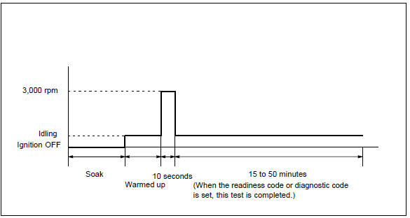
- Drive pattern
- connect the obd ii scan tool to dlc3 to check monitor status and preconditions.
- Release pressure in the fuel tank by removing and then reinstalling the fuel tank cap.
- Start the engine and allow it to idle until ect becomes 167°f (75 °C) or greater.
- Run the engine at 3,000 rpm for about 10 seconds.
- Allow the engine to idle with the a/c on (to create slight load) for 15 to 50 minutes.
Notice
: if the vehicle is not equipped with a/c put a slight load on the engine by doing the following :
- securely set the parking brake.
- Block the drive wheels with wheel chocks.
- Allow the vehicle to idle in drive for 15 to 50 minutes.


Other materials:
Inspection procedure
Hint:
start the inspection from step 1 in case of using the hand–held tester and start
from step 2 in case of not
using the hand–held tester.
1 Perform active test by hand–held tester(abs motor relay)
Check the operation sound of the abs motor individually when operaing it
with the ...
Replacement
Hint: components:
1. Precaution
2. Disconnect battery negative terminal
3. Remove parking brake hole cover sub–assy
4. Remove floor shift shift lever knob sub–assy (m/t transaxle)
5. Remove shifting hole cover sub–assy (m/t transaxle)
6. Remove console panel upper
7. Remove conso ...
Data list/active test
1. Data list
Hint:
using the data list displayed by the hand–held tester or the obd ii scan tool,
you can read the value of
the switches, sensors, actuators and so on without parts removal. Reading the
data list as a first step
of troubleshooting is one method to shorten diagnostic time.
...