
Toyota Corolla (E120) 2002–2008 Repair Manual / Diagnostics / Supplemental restraint system / Short in p/t squib (rh) circuit (to b+) / Inspection procedure
Toyota Corolla (E120): Inspection procedure
1 Check p/t squib(rh) circuit(airbag sensor assy center – front seat outer belt assy rh)
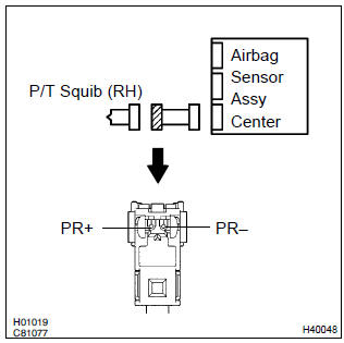
- Disconnect the negative (–) terminal cable from the battery, and wait at least for 90 seconds.
- disconnect the connectors between the airbag sensor assy center and the seat belt pretensioner (rh).
- connect the negative (–) terminal cable to the battery, and wait at least for 2 seconds.
- turn the ignition switch to on.
- for the connector (on the seat belt pretensioner side) between
the airbag sensor assy center and the seat belt pretensioner
(rh), measure the voltage between pr+ and
body ground.
Ok: voltage: below 1v


2 Check air bag sensor assy center
Sst 09843–18040
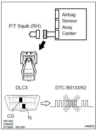
- Turn the ignition switch to lock.
- disconnect the negative (–) terminal cable from the battery, and wait at least for 90 seconds.
- connect the connector to the airbag sensor assy center.
- using a service wire, connect pr+ and pr– of the connector (on the seat belt pretensioner side) between the airbag sensor assy center and the seat belt pretensioner (rh).
- connect the negative (–) terminal cable to the battery, and wait at least for 2 seconds.
- turn the ignition switch to on, and wait at least for 20 seconds.
- clear the dtc stored in memory .
- turn the ignition switch to lock, and wait at least for 20 seconds.
- turn the ignition switch to on, and wait at least for 20 seconds.
- check the dtc .
Ok: dtc b0133/62 is not output.
Hint
: codes other than code b0133/62 may be output at this time, but they are not relevant to this check.


3 Check p/t squib (rh)
Sst 09843–18040
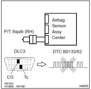
- Turn the ignition switch to lock.
- disconnect the negative (–) terminal cable from the battery, and wait at least for 90 seconds.
- connect the seat belt pretensioner (rh) connector.
- connect the negative (–) terminal cable to the battery, and wait at least for 2 seconds.
- turn the ignition switch to on, and wait at least for 20 seconds.
- clear the dtc stored in memory .
- turn the ignition switch to lock, and wait at least for 20 seconds.
- turn the ignition switch to on, and wait at least for 20 seconds.
- check the dtc .
Ok: dtc b0133/62 is not output.
Hint
: codes other than code b0133/62 may be output at this time, but they are not relevant to this check.


4 Use simulation method to check


Replace all srs components including the wire harness


Other materials:
AUX port/USB port
Connect an iPod, USB memory device or portable audio player to the AUX port/USB
port as indicated below. Press to select
“iPod”, “USB” or “AUX”.
Connecting using the AUX port/USB port
■ iPod
Open the cover and connect an iPod using an iPod cable.
Turn on the power of the i ...
Inspection procedure
1 Check p/t squib(lh) circuit(airbag sensor assy center – front seat
outer belt assy lh)
Disconnect the negative (–) terminal cable from the battery,
and wait at least for 90 seconds.
disconnect the connectors between the airbag sensor
assy center and the seat belt pretensio ...
Inspection procedure
1 Check p squib circuit(airbag sensor assy center – instrument
panel passenger airbag assy)
Disconnect the negative (–) terminal cable from the battery,
and wait at least for 90 seconds.
disconnect the connectors between the airbag sensor
assy center and the instrument panel ...