Toyota Corolla (E120) 2002–2008 Repair Manual / Diagnostics / Sfi system / Diagnosis system / Description
Toyota Corolla (E120): Description
- When troubleshooting obd ii vehicles, the only difference from the usual troubleshooting procedure is that you need to connect the vehicle to the obd ii scan tool complying with sae j1978 or the hand–held tester, and read various data output from the vehicle’s ecm.
- Obd ii regulations require that the vehicle’s on–board computer illuminates the malfunction indicator light (mil) on the instrument panel when the computer detects a malfunction in the emission control system/components or in the powertrain control components which affect vehicle emissions, or a malfunction in the computer. In addition to the mil illuminating when a malfunction is detected, the applicable diagnostic trouble codes (dtcs) prescribed by sae j2012 are recorded in the ecm memory .
If the malfunction does not reoccur in 3 consecutive trips, the mil goes off automatically but the dtcs remain recorded in the ecm memory.
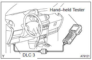
- To check the dtc, connect the hand–held tester or obd
ii scan tool to the data link connector 3 (dlc3) of the vehicle.
The hand–held tester or obd ii scan tool also enables you to erase the dtc and check the freeze frame data and various forms of engine data (for operating instructions, see the obd ii scan tool’s instruction book).
The dtc includes sae controlled codes and manufacturer controlled codes. Sae controlled codes must be set as prescribed by the sae, while manufacturer controlled codes can be set freely by a manufacturer within the prescribed limits (see the dtc chart on page 05–35).
- The diagnosis system operates in the normal mode during normal vehicle use. It also has a check mode for technicians to simulate malfunction symptoms and troubleshoot it. Most dtcs use the 2 trip detection logic* to prevent erroneous detection, and to ensure a thorough malfunction detection. By switching the ecm to the check mode when troubleshooting, a technician can cause the mil to illuminate for a malfunction that is only detected once or momentarily (hand–held tester only) (1).
- *2 Trip detection logic: when a malfunction is first detected, the malfunction is temporarily stored in the ecm memory (1st trip). If the same malfunction is detected again during the second drive test, this second detection causes the mil to illuminate (2nd trip) (however, the ignition switch must be turned off between the 1st trip and 2nd trip).
- Freeze frame data: the freeze frame data records the engine conditions (fuel system, calculated load, engine coolant temperature, fuel trim, engine speed, vehicle speed, etc.) When a malfunction is detected. When troubleshooting, it is useful for determining whether the vehicle was running or stopped, the engine was warmed up or not, the air–fuel ratio was lean or rich, etc. At the time of the malfunction.
Priorities for troubleshooting: if troubleshooting priorities for multiple dtcs are given in the applicable dtc chart, these priorities should be followed.
If no instructions are given, perform troubleshooting for those dtcs according to the following priorities.
- dtcs other than fuel trim malfunction (dtcs p0171 and p0172) and misfire (dtcs p0300 to p0304).
- fuel trim malfunction (dtcs p0171 and p0172).
- misfire (dtcs p0300 to p0304).


Other materials:
Favorites list setting
Up to 15 contacts (maximum of 4 numbers per contact) can be registered in the
favorites list.
■ Registering the contacts in the favorites list
1 Select “Add Favorite”.
2 Select the desired contact to add to the favorites list.
Dimmed contacts are already stored as a favorite.
3 Chec ...
Radio receiver assy
Replacement
Рint: components:
1. Remove floor shift shift lever knob sub–assy (m/t transaxle)
2. Remove console panel upper
3. Remove heater control knob
4. Remove instrument cluster finish panel
5. Remove instrument cluster finish panel sub–assy
center
Remove the 4 screws.
& ...
Location
...