Toyota Corolla (E120) 2002–2008 Repair Manual / Diagnostics / Sfi system / Diagnosis system / Check dlc3
Toyota Corolla (E120): Check dlc3
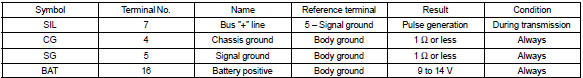
The vehicle’s ecm uses the iso 9141–2 for communication protocol. The terminal arrangement of the dlc3 complies with sae j1962 and matches the iso 9141–2 format.
Hint
: if the display shows unable to connect to vehicle when you have connected the cable of the obd ii scan tool or the hand–held tester to the dlc3, turned the ignition switch on and operated the scan tool, there is a problem on the vehicle side or tool side.
- If the communication is normal when the tool is connected to another vehicle, inspect the dlc3 on the original vehicle.
- If the communication is still impossible when the tool is connected to another vehicle, the problem is probably in the tool itself, so consult the service department listed in the tool’s instruction manual.
Inspect battery voltage
Battery voltage: 11 to 14 v
If voltage is below 11 v, recharge the battery before proceeding.
Check mil
- The mil comes on when the ignition switch is turned on
and the engine is not running.
Hint
: if the mil is not illuminated, troubleshoot the mil circuit .
- when the engine is started, the mil should go off. If the mil remains on, it means that the diagnosis system has detected a malfunction or abnormality in the system.


Other materials:
Shift lock system (atm)
On–vehicle inspection
1. Check shift lock operation
shift the shift lever to p position.
turn the ignition switch to lock.
check that the shift lever cannot be shifted to any other
positions other than p.
turn the ignition switch to on, depress the brake pedal ...
Replacement
1. Remove clutch start switch assy
disconnect the clutch start switch assy connector.
remove the nut and clutch start switch assy from the clutch pedal
support.
2. Install clutch start switch assy
install the clutch start switch assy with the nut.
Torque: 15.68 Nv ...
Evap monitor (vacuum pressure monitor)
Notice:
a cold soak must be performed prior to conducting the drive pattern to complete
the internal pressure
readiness monitor.
Cold soak preconditions
The monitor will not run unless:
mil is off.
Fuel level is approximately 1/2 to 3/4.
Altitude is 7800 feet (2400 m) or less.
...