Toyota Corolla (E120): Dtc check/clear
Notice
:
- if there is no dtc in the normal mode, check the pending fault code using the continuous test results function (mode 7 for sae j1979) on the obd ii scan tool or the hand–held tester.
- Hand–held tester only: when the diagnosis system is switched from the normal mode to the check mode, all the dtcs and freeze frame data recorded in the normal mode will be erased. So before switching modes, always check the dtcs and freeze frame data, and then write them down.
1. Check dtc (using the obd ii scan tool or hand–held tester)
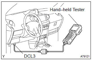
- Connect the obd ii scan tool or hand–held tester to the dlc3.
- turn the ignition switch on.
- use the obd ii scan tool or the hand–held tester to check
the dtcs and freeze frame data and then write them
down. If you need help with the obd ii scan tool, refer to
the scan tool’s instruction book.
If there is no dtc in the normal mode, check the pending fault code using the continuous test results function on the obd ii scan tool or the hand–held tester.
- to confirm the details of the dtcs.
Notice
:
- when simulating a symptom with the obd ii scan tool (excluding hand–held tester) to check the dtcs, use the normal mode. For code on the dtc chart subject to the ”2 trip detection logic”, perform either of the following actions.
- Turn the ignition switch off after the symptom is simulated once. Then repeat the simulation process again. When the problem has been simulated twice, the mil lights up and the dtcs are recorded in the ecm.
- Check the pending fault code using the continuous test results function on the obd ii scan tool.
2. Clear dtc (using the obd ii scan tool or hand–held tester)
- Connect the obd ii scan tool or the hand–held tester to the dlc3.
- turn the ignition switch on.Operate the obd ii scan tool or the hand–held tester to erase the codes. All the dtcs and freeze frame data will be erased. (See the obd ii scan tool’s instruction book for operating instructions.)
3. Clear dtc (not using the obd ii scan tool or hand– held tester)
- Disconnect the battery terminal or remove the efi fuse from the engine room r/b for more than 60 seconds.


Other materials:
Exhaust gas precautions
Harmful substance to the human body is included in exhaust gases if inhaled.
CAUTION
Exhaust gases include harmful carbon monoxide (CO), which is colorless and odorless.
Observe the following precautions.
Failure to do so may cause exhaust gases enter the vehicle and may lead to an
accident c ...
Warning lights
Warning lights inform the driver of malfunctions in the indicated vehicle’s systems.
*1: Vehicles without a smart key system:
These lights turn on when the engine switch is turned to the “ON” position to indicate
that a system check is being performed. They will turn off after the engi ...
Definition of terms
Term
Definition
Monitor description
Description of what the ecm monitors and how it detects malfunction
(monitoring purpose and its details).
Related dtcs
Diagnostic code
Typical enabling condition
Preconditions that allow the ecm to detect m ...