
Toyota Corolla (E120): Check mode procedure
Hint
: hand–held tester only: compared to the normal mode, the check mode has more sensing ability to detect malfunctions. Furthermore, the same diagnostic items which are detected in the normal mode can also be detected in the check mode.
1. Check mode procedure(using the hand–held tester)
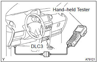
- Check the initial conditions.
- Battery positive voltage 11 v or more
- throttle valve fully closed
- transmission in the p or n position
- a/c switched off
- turn the ignition switch off.
- connect the hand–held tester to the dlc3.
- turn the ignition switch on.
- switch the hand–held tester from the normal mode to the check mode (check that the mil flashes).
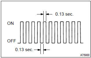
Notice
: if the hand–held tester switches the ecm from the normal mode to the check mode or vice–versa, or if the ignition switch is turned from on to acc or off during the check mode, the dtc and freeze frame data will be erased.
- Start the engine (mil goes off after the engine starts).
- simulate the conditions of the malfunction described by the customer.
Notice
: leave the ignition switch on until you have checked the dtc, etc.
- After simulating the malfunction conditions, check the dtc and freeze frame data, etc using the hand–held tester diagnosis selector.
Hint
: do not turn the ignition switch off, as turning it off switches the diagnosis system from the check mode to the normal mode, which erases all the dtcs, etc.
- After checking the dtc, inspect the applicable circuit.
2. Clear dtc (using the obd ii scan tool or hand–held tester)
- Connect the obd ii scan tool or hand–held tester to the dlc3.
- turn the ignition switch on.
- operate the obd ii scan tool or hand–held tester to erase the codes. All the dtcs and freeze frame data will be erased. (See the obd ii scan tool’s instruction book for operating instructions.)
3. Clear dtc (not using the obd ii scan tool or hand– held tester)
- Disconnect the battery terminal or remove the efi fuse from the engine room r/b for more than 60 seconds.


Other materials:
Air outlets
■ Location of air outlets
The air outlets and air volume changes according to the selected airflow mode.
: Some models
■ Adjusting the position of and opening and closing the air outlets
► Front center outlets
Direct air flow to the left or right, up or down.
► Fro ...
Rear suspension
Preparation
Sst
Recomended tools
Equipment
Tire & wheel
Preparation
Equipment
...
Outer rear view mirror assy lh
Replacement
Hint:
installation is according to the reverse order of the removal.
In the rh side, work in the same procedure as in the lh side.
1. Remove front armrest assy lh
2. Remove power window regulator master switch assy (w/ power window)
3. Remove front armrest base panel upper ...