Toyota Corolla (E120): Basic inspection
When the malfunction is not confirmed in the dtc check, troubleshooting should be carried out in all the possible circuits considered as causes of the problem. In many cases, by carrying out the basic engine check shown in the following flowchart, the location causing the problem can be found quickly and efficiently. Therefore, using this check is essential in the engine troubleshooting.
1 Check battery voltage
Notice
: carry out this check with the engine stopped and ignition switch off.
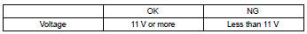
Ng charge or replace battery

2 Check if engine will crank
Ng proceed to problem symptoms table on page
3 Check if engine starts
Ng go to step 7
4 Check air filter
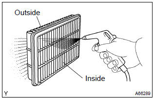
- Visually check that the air filter is not excessively dirty or oily.
Notice
: if necessary, clean the filter with compressed air. First blow from the inside thoroughly, then blow from the outside of the filter.
Ng clean or replace
5 Check idle speed
Ng proceed to problem symptoms table on page
6 Check ignition timing
Ng proceed to page 14–1 and continue to troubleshoot
Proceed to problem symptoms table on page
7 Check fuel pressure
Ng proceed to page 11–1 and continue to troubleshoot
8 Check for spark
Ng proceed to page 18–1 and continue to troubleshoot
Proceed to problem symptoms table on page


Other materials:
Circuit description
Refer to dtc p0115
Dtc no.
Dtc detection condition
Trouble area
P0125
If the engine coolant temperature (ect) was less than –6.6 °C
(20 °F) when starting the engine, and 20 minutes after the engine
start, the ect sensor still indicates below 20 °C (68 ...
Inspection procedure
1 Check operation(overdrive)
Drive the vehicle after the engine warms up.
check that overdrive on e off occurs by an operation of the o/d
switch on–off.
2 Inspect terminal voltage(od)
Remove the cruise control ecu assy with the connector
still connected.
tur ...
Key confinement prevention function does not work
properly (unlock warning switch circuit)
Circuit description
The unlock warning switch turns on when the key is inserted in the ignition
key cylinder and the door courtesy
switch turns on when the driver’s door is opened, and the integration relay
monitors both switches conditions.
According to these switches conditions, the int ...