Toyota Corolla (E120): Replacement
Hint
: installation is in the reverse order of the removal. But the installation is indicated only when it has a point.
1. Remove spare wheel cover assy
2. Remove rear floor finish plate
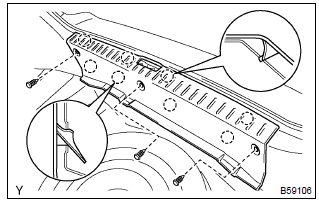
- Remove the 3 clips.
- using a moulding remover, remove the rear floor finish plate.
3. Remove luggage compartment trim cover inner lh
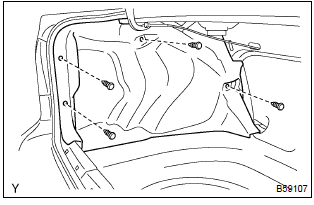
- Remove the 4 clips and the luggage compartment trim cover.
- employ the same manner described above to the other side.
4. Remove luggage compartment trim cover inner rh
5. Disconnect rear bumper side seal lh
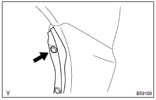
- Remove the clip and a part of the rear bumper side seal,
as shown in the illustration.
Hint
: do not remove the lower side clip.
- employ the same manner described above to the other side.
6. Disconnect rear bumper side seal rh
7. Remove rear bumper cover
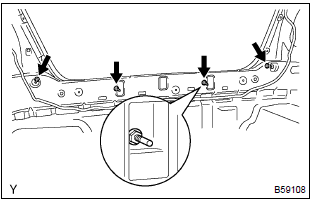
- Remove the 4 nuts.
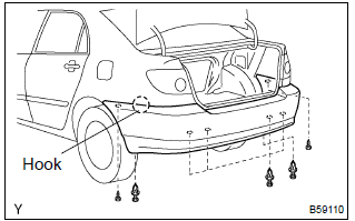
- Remove the 2 screws and 6 clips.
- disengage the hook, and remove the rear bumper cover.
8. Remove rear bumper energy absorber
9. Remove rear bumper reinforcement no.2
- remove the rear bumper reinforcement no. 2 From the rear bumper energy absorber.
10. Remove rear no.2 Spoiler sub–assy (w/ rear spoiler)
- remove the 5 retainers, screw and the rear spoiler.
- employ the same manner described above to the other side.
11. Remove rear no.1 Spoiler sub–assy (w/ rear spoiler)
12. Remove bumper moulding set bolt no.1
13. Remove rear bumper reinforcement no.1
- remove the 4 nuts and rear bumper reinforcement no. 1.
14. Remove rear bumper arm lh
- remove the 3 bolts and rear bumper arm.
- employ the same manner described above to the other side.
15. Remove rear bumper arm rh
16. Install rear bumper arm lh
- install the rear bumper arm with the 3 bolts.
Torque: 36 nvm (367 kgfvcm, 27 ftvlbf)
- employ the same manner described above to the other side.
17. Install rear bumper arm rh
18. Install rear bumper reinforcement no.1
- install the rear bumper reinforcement no. 1 With the 4 nuts.
Torque: 36 nvm (367 kgfvcm, 27 ftvlbf)
19. Install rear bumper cover
- install the rear bumper cover with the 2 screws, 8 clips and 4
nuts.
Torque: 5.5 Nvm (56 kgfvcm, 49 in.Vlbf) for nuts
Other materials:
Timing gear cover oil seal
Replacement
1. Remove engine under cover rh
2. Remove front wheel rh
3. Remove fan and generator v belt
Turn the v–ribbed belt tensioner slowly clockwise and
loosen it. Then, remove the fan and generator belt v and
put back the v–ribbed belt tensioner little by little and fix
it ...
Positioning a floor jack
When using a floor jack, follow
the instructions in the
manual provided with the
jack and perform the operation
safely.
When raising your vehicle
with a floor jack, position
the jack correctly. Improper
placement may damage
your vehicle or cause injury.
Location of the jack point
■ Front
■ Rea ...
Fuel information
You must only use unleaded gasoline in your vehicle.
Select octane rating 87 (Research Octane Number 91) or higher.
Use of unleaded gasoline with an octane rating lower than 87 may result in engine
knocking. Persistent knocking can lead to engine damage.
At minimum, the gasoline you use should ...


