Toyota Corolla (E120): Circuit inspection
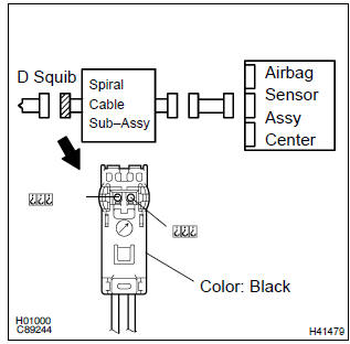
1 Check d squib circuit(airbag sensor assy center – horn button assy)
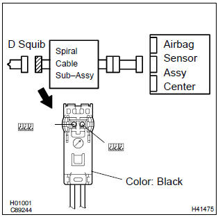
- Disconnect the negative (–) terminal cable from the battery, and wait at least for 90 seconds.
- disconnect the connectors between the airbag sensor assy center and the horn button assy.
- connect the negative (–) terminal cable to the battery, and wait at least for 2 seconds.
- turn the ignition switch to on.
- for the black connector (on the spiral cable sub–assy
side) between the horn button assy and the spiral cable
sub–assy, measure the voltage between d2+ and body
ground.
Ok: voltage: below 1 v


2 Check air bag sensor assy center
Sst 09843–18040
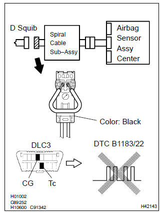
- Turn the ignition switch to lock.
- disconnect the negative (–) terminal cable from the battery, and wait at least for 90 seconds.
- connect the connector to the airbag sensor assy center.
- using a service wire, connect d2+ and d2– of the black connector (on the spiral cable sub–assy side) between the horn button assy and the spiral cable sub–assy.
- connect the negative (–) terminal cable to the battery, and wait at least for 2 seconds.
- turn the ignition switch to on, and wait at least for 20 seconds.
- clear the dtc stored in memory .
- turn the ignition switch to lock, and wait at least for 20 seconds.
- turn the ignition switch to on, and wait at least for 20 seconds.
- check the dtc .
Ok: dtc b1183/22 is not output.
Hint
: codes other than code b1183/22 may be output at this time, but they are not relevant to this check.


3 Check d squib
Sst 09843–18040
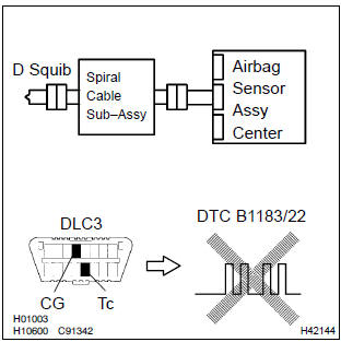
- Turn the ignition switch to lock.
- disconnect the negative (–) terminal cable from the battery, and wait at least for 90 seconds.
- connect the horn button assy connectors.
- connect the negative (–) terminal cable to the battery, and wait at least for 2 seconds.
- turn the ignition switch to on, and wait at least for 20 seconds.
- clear the dtc stored in memory .
- turn the ignition switch to lock, and wait at least for 20 seconds.
- turn the ignition switch to on, and wait at least for 20 seconds.
- check the dtc .
Ok: dtc b1183/22 is not output.
Hint
: codes other than code b1183/22 may be output at this time, but they are not relevant to this check.


4 Use simulation method to check


Replace all srs components including the wire harness
5 Check instrument panel wire(airbag sensor assy center – spiral cable sub–assy)
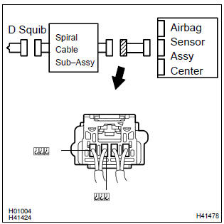
- Turn the ignition switch to lock.
- disconnect the connector of the instrument panel wire.
- turn the ignition switch to on.
- ) for the connector (on the spiral cable sub–assy side) between
the horn button assy and the spiral cable sub–assy,
measure the voltage between d2+ and body ground.
Ok: voltage: below 1 v

6 Check spiral cable sub–assy
- For the black connector (on the spiral cable sub–assy
side) between the horn button assy and the spiral cable
sub–assy, measure the voltage between d2+ and body
ground.
Ok: voltage: below 1 v


7 Use simulation method to check


Replace all srs components including the wire harness


Other materials:
Inspection procedure
1 Inspect dlc3 terminal voltage
Turn the ignition switch to on.
measure voltage between terminals 13 (tc) and 4 (cg) of
dlc3.
Ok:
voltage: 10 – 16 v
2 Check harness and connector(between cruise control ecu assy
and dlc3)
Check for open and short circuit in harness ...
Replacement
1. Drain engine oil
remove the oil pan drain plug and drain the engine oil.
2. Removal & installation chain sub–assy
3. Remove chain vibration damper no.1
remove 2 bolts and chain vibration damper no. 1.
4. Remove oil pump assy
Remove the 5 bolts.
rem ...
What to do if... (Troubleshooting)
If there is a problem with the hands-free system or a Bluetooth® device, first
check the table below.
► When using the hands-free system with a
Bluetooth® device
► When registering/connecting a cellular
phone
► When making/receiving a call
► When using the p ...