
Toyota Corolla (E120) 2002–2008 Repair Manual / Diagnostics / ABS with EBD system / Ts terminal circuit / Circuit description
Toyota Corolla (E120): Circuit description
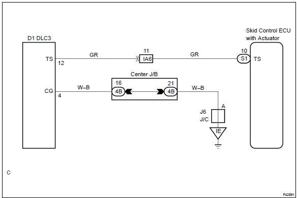
The sensor check circuit detects abnormalities in the speed sensor signal which cannot be detected with the dtc check.
Connecting terminals ts and cg of the dlc3 starts the check.
Wiring diagram


Other materials:
Inspection procedure
1 Inspect skid control ecu connector(+bs terminal voltage)
Disconnect the skid control ecu connector.
measure the voltage between terminals +bs (2) and gnd
(1, 23) of skid control ecu harness side connector.
Voltage: 10 – 14 v
2 Reconfirm dtc
Check the dtc .
Ok :
...
Maintenance requirements
To ensure safe and economical
driving, day-to-day care
and regular maintenance
are essential. It is the
owner's responsibility to
perform regular checks.
Toyota recommends the
maintenance below.
■Repair and replacement
It is recommended that genuine
Toyota parts be used for repairs to
ensure perf ...
Steering wheel audio switches
Some audio features can be controlled using the switches on the steering wheel.
Operation may differ depending on the type of audio system or navigation system.
For details, refer to the manual provided with the audio system or navigation system.
Operating the audio system using the steering whe ...