Toyota Corolla (E120) 2002–2008 Repair Manual / Diagnostics / Sfi system / Crankshaft position – camshaft
position correlation / Circuit description
Toyota Corolla (E120): Circuit description
Refer to dtc p0335
|
Dtc no. |
Dtc detection condition |
Trouble area |
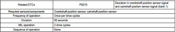
| P0016 | Deviation in crankshaft position sensor signal and camshaft position sensor signal (2 trip detection logic) |
|
Monitor description
The ecm optimizes the valve timing using the variable valve timing (vvt) system to control the intake valve camshaft. The vvt system includes the ecm, the oil control valve (ocv) and the vvt controller. The ecm sends a target ”duty–cycle” control signal to the ocv. This control signal, applied to the ocv, regulates the oil pressure supplied to the vvt controller. The vvt controller can advance or retard the intake valve camshaft.
The ecm calibrates the valve timing of the vvt system by setting the camshaft to the maximum retard angle when the engine speed is idling. The ecm closes the ocv to retard the cam. The ecm stores this valve as ”vvt learned value” (when the difference between the target valve timing and the actual valve timing is 5 or less, the ecm learns it).
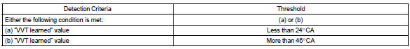
If the learned value meets both of the following conditions (”a” and ”b”), the ecm interprets this as a defect in the vvt system and set a dtc.
- ”vvt learning” value is less than 24 ca, or more than 46 ca.
- above condition continues for more than 18 seconds.
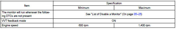
Monitor strategy
Typical enabling conditions
Typical malfunction thresholds
Wiring diagram
Refer to dtc p0335


Other materials:
Unlocking and locking the doors from the outside
◆ Smart key system (if equipped)
Carry the electronic key to enable this function.
1 Grip the driver’s door handle to unlock the door. Grip the passenger’s door
handle to unlock all the doors.* Make sure to touch the sensor on the back of the
handle.
The doors cannot be unlocked for ...
Inspection procedure
1 Check side squib(lh) circuit(airbag sensor assy center – front
seat airbag assy lh)
Disconnect the negative (–) terminal cable from the battery,
and wait at least for 90 seconds.
disconnect the connectors between the airbag sensor
assy center and the front seat airbag assy ...
How to check and change detailed Bluetooth® settings
1 Display the “Bluetooth* Setup” screen.
2 Select “System Settings”.
3 The following screen is displayed:
1 Bluetooth® Power on/off
You can change Bluetooth® function on/off
2 Bluetooth® Name
3 Change PIN-code
4 Bluetooth® Address
5 Display Phone Status
You can set the system ...