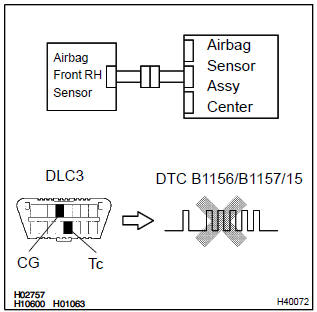
Toyota Corolla (E120) 2002–2008 Repair Manual / Diagnostics / Supplemental restraint system / Front airbag sensor (rh)
malfunction / Inspection procedure
Toyota Corolla (E120): Inspection procedure
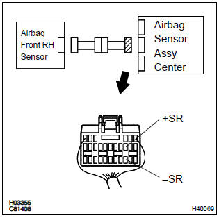
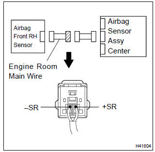
1 Check front airbag sensor (rh) circuit (to b+)(airbag sensor assy center – airbag front rh sensor)
- Disconnect the negative (–) terminal cable from the battery, and wait at least for 90 seconds.
- disconnect the connectors between the airbag front rh sensor and the airbag sensor assy center.
- connect the negative (–) terminal cable to the battery, and wait at least for 2 seconds.
- turn the ignition switch to on.
- for the connector (on the airbag sensor assy center side)
between the airbag front rh sensor and the airbag sensor
assy center, measure the voltage between body
ground and each of +sr and –sr.
Ok: voltage: below 1 v


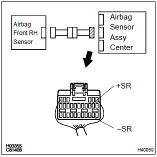
2 Check front airbag sensor (rh) circuit (to ground)(airbag sensor assy – airbag front rh sensor)
- Turn the ignition switch to lock.
- disconnect the negative (–) terminal cable from the battery, and wait at least for 90 seconds.
- for the connector (on the airbag sensor assy center side)
between the airbag front rh sensor and the airbag sensor
assy center, measure the resistance between body
ground and each of +sr and –sr.
Ok: resistance: 1 mΩ or higher


3 Check front airbag sensor (rh) circuit(open)(airbag sensor assy center – airbag front rh sensor)
Sst 09843–18040
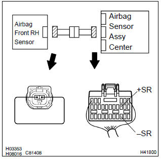
- Using a service wire, connect +sr and –sr of the connector (on the airbag front rh sensor side) between the airbag front rh sensor and the airbag sensor assy center.
- for the connector (on the airbag sensor assy center side)
between the airbag front rh sensor and the airbag sensor
assy center, measure the resistance between +sr
and –sr.
Ok: resistance: below 1 Ω


4 Inspect air bag front rh sensor
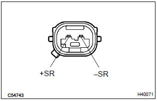
- For the connector of the airbag front rh sensor, measure
the resistance between +sr and –sr.
Ok: resistance: 820 Ω


5 Check air bag sensor assy center
Sst 09843–18040
- Disconnect the negative (–) terminal cable from the battery, and wait at least for 90 seconds.
- connect the airbag front rh sensor connector and airbag sensor assy center connector.
- connect the negative (–) terminal cable to the battery, and wait at least for 2 seconds.
- turn the ignition switch to on, and wait at least for 20 seconds.
- clear the dtc stored in memory .
- turn the ignition switch to lock, and wait at least for 20 seconds.
- turn the ignition switch to on, and wait at least for 20 seconds.
- check the dtc .
Ok: dtc b1156/b1157/15 is not output.
Hint
: codes other than code b1156/b1157/15 may be output at this time, but they are not relevant to this check.


Use simulation method to check
6 Check engine room main wire harness (to b+)(connector – airbag front rh sensor)
- Turn the ignition switch to lock.
- disconnect the negative (–) terminal cable from the battery, and wait at least for 90 seconds.
- disconnect the connector between the engine room main wire and the instrument panel wire.
- connect the negative (–) terminal cable to the battery, and wait at least for 2 seconds.
- turn the ignition switch to on.
- for the engine room main wire connector (on the airbag
sensor assy center side) between the airbag sensor assy
center and the airbag front rh sensor, measure the voltage
between body ground and each of +sr and –sr.
Ok: voltage: below 1 v
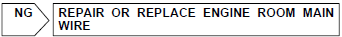

Repair or replace instrument panel wire
7 Check engine room main wire harness (to ground)(connector – airbag front rh sensor)
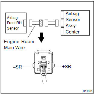
- Disconnect the connectors between the engine room main wire and the instrument panel wire.
- for the engine room main wire connector (on the airbag
sensor assy center side) between the airbag sensor assy
center and the airbag front rh sensor, measure the resistance
between body ground and each of +sr and –sr.
Ok: resistance: 1 mΩ or higher

Repair or replace instrument panel wire
8 Check engine room main wire harness(open)(connector – airbag front rh sensor)
Sst 09843–18040
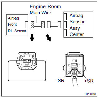
- Disconnect the connectors between the engine room main wire and the instrument panel wire.
- using a service wire, connect +sr and –sr of the engine room main wire connector (on the airbag front rh sensor side) between the airbag sensor assy center and the airbag front rh sensor.
- for the engine room main wire connector (on the airbag
sensor assy center side) between the airbag sensor assy
center and the airbag front rh sensor, measure the resistance
between the +sr and –sr.
Ok: resistance: below 1 Ω

Repair or replace instrument panel wire


Other materials:
Installing child restraints using a seat belt
■ Rear-facing - Infant seat/convertible seat
1 Place the child restraint system on the rear seat facing the rear of the vehicle.
2 Run the seat belt through the child restraint system and insert the plate into
the buckle. Make sure that the belt is not twisted.
3 Fully extend the shou ...
Description
1. Radio wave band
The radio wave bands used in radio broadcasting are as follows:
Lf: low frequency
mf: medium frequency
hf: high frequency
vhf: very high frequency
2. Service area
There are great differences in the size of the service area
for am and fm broadcasting. Sometimes ...
Using the voice command system (Multimedia system)
Voice command system
The voice command system enables the hands-free system to be operated using
voice commands.
Operations of the voice command system can be performed by selecting the menu
corresponding to each function on the screen. Even if any menu is selected, commands
displayed on all ...