Toyota Corolla (E120) 2002–2008 Repair Manual / Diagnostics / Supplemental restraint system / Short in d squib circuit / Inspection procedure
Toyota Corolla (E120): Inspection procedure
1 Check d squib circuit(airbag sensor assy center – horn button assy)
- Disconnect the negative (–) terminal cable from the battery, and wait at least for 90 seconds.
- disconnect the connectors between the airbag sensor assy center and the horn button assy.
- release the airbag activation prevention mechanism of the connector (on the airbag sensor assy center side) between the airbag sensor assy center and the spiral cable sub–assy .
- for the connector (on the spiral cable sub–assy side) between
the horn button assy and the spiral cable sub–assy,
measure the resistance between d+ and d–.
Ok: resistance: 1 mw or higher


2 Check air bag sensor assy center
Sst 09843–18040
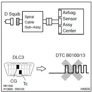
- Connect the connector to the airbag sensor assy center.
- connect the negative (–) terminal cable to the battery, and wait at least for 2 seconds.
- turn the ignition switch to on, and wait at least for 20 seconds.
- clear the dtc stored in memory .
- turn the ignition switch to lock, and wait at least for 20 seconds.
- turn the ignition switch to on, and wait at least for 20 seconds.
- check the dtc .
Ok: dtc b0100/13 is not output.
Hint
: codes other than code b0100/13 may be output at this time, but they are not relevant to this check.


3 Check d squib
Sst 09843–18040
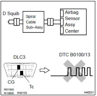
- Turn the ignition switch to lock.
- disconnect the negative (–) terminal cable from the battery, and wait at least for 90 seconds.
- connect the horn button assy connectors.
- connect the negative (–) terminal cable to the battery, and wait at least for 2 seconds.
- turn the ignition switch to on, and wait at least for 20 seconds.
- clear the dtc stored in memory .
- turn the ignition switch to lock, and wait at least for 20 seconds.
- turn the ignition switch to on, and wait at least for 20 seconds.
- check the dtc .
Ok: dtc b0100/13 is not output.
Hint: codes other than code b0100/13 may be output at this time, but they are not relevant to this check.


Use simulation method to check
4 Check instrument panel wire(airbag sensor assy center – spiral cable sub–assy)
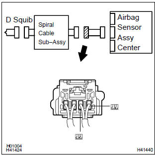
- Disconnect the connector of the instrument panel wire.
- release the airbag activation prevention mechanism of the connector (on the airbag sensor assy center side) between the airbag sensor assy center and the spiral cable sub–assy .
- for the connector (on the spiral cable sub–assy side) between
the airbag sensor assy center and the spiral cable
sub–assy, measure the resistance between d+ and d–.
Ok: resistance: 1 mΩ or higher

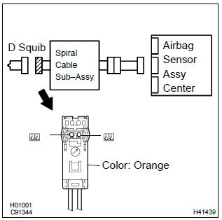
5 Check spiral cable sub–assy
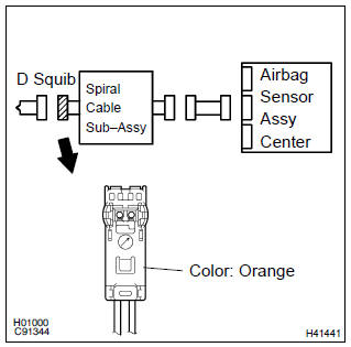
- Release the airbag activation prevention mechanism of the spiral cable sub–assy connector on the airbag sensor assy center side .
- for the orange connector (on the spiral cable sub–assy
side) between the horn button assy and the spiral cable
sub–assy, measure the resistance between d+ and d–.
Ok: resistance: 1 mΩ or higher


Use simulation method to check


Other materials:
Rear speaker assy
Replacement
Hint: components:
1. Remove rear door opening trim rh
2. Remove rear door opening trim lh
3. Remove bench type rear seat cushion assy( or 72–8)
4. Remove rear seat back assy (fixed type rear seat)
5. Remove rear seat back assy (separated type rear seat)
6. Remove rear seat side ...
Overhaul
Notice:
when using a vise, do not over tighten.
When installing, coat the parts indicated by the arrows with power
steering fluid .
1. Remove front wheel rh
2. Drain power steering fluid
3. Remove engine under cover rh
4. Remove fan and generator v belt
5. Disconnect oil reservoir to ...
Fog light switch
The fog lights secure excellent visibility in difficult driving conditions,
such as in rain and fog.
1 Turns the front fog lights off
2 Turns the front fog lights on
*1: For U.S.A.
*2: For Canada
■Fog lights can be used when
The headlights are on in low beam. ...