Toyota Corolla (E210) 2019-2026 Owners Manual / For safety and security / For safe use / Before driving
Toyota Corolla (E210): Before driving
Observe the following before starting off in the vehicle to ensure safety of driving.
Floor mat
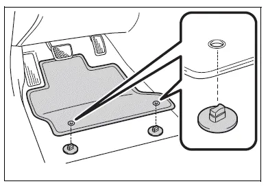
Use only floor mats designed specifically for vehicles of the same model and model year as your vehicle. Fix them securely in place onto the carpet.
1. Insert the retaining hooks (clips) into the floor mat eyelets.
2. Turn the upper knob of each retaining hook (clip) to secure the floor mats in place.
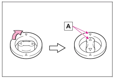
Always align the  marks A.
The shape of the retaining hooks (clips) may differ from that shown in the illustration.
WARNING
Observe the following precautions.
Failure to do so may cause the driver's floor mat to slip, possibly interfering with the pedals while driving. An unexpectedly high speed may result or it may become difficult to stop the vehicle.
This could lead to an accident, resulting in death or serious injury.
■When installing the driver's floor mat
- Do not use floor mats designed for other models or different model year vehicles, even if they are Toyota Genuine floor mats.
- Only use floor mats designed for the driver's seat.
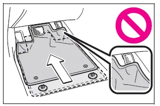
- Always install the floor mat securely using the retaining hooks (clips) provided.
- Do not use two or more floor mats on top of each other.
- Do not place the floor mat bottom- side up or upside-down.
■Before driving
- Check that the floor mat is securely fixed in the correct place with all the provided retaining hooks (clips). Be especially careful to perform this check after cleaning the floor.
- With the engine stopped and the shift lever in P, fully depress each pedal to the floor to make sure it does not interfere with the floor mat.


Other materials:
Out side moulding
Replacement
Hint:
use the same procedures for the rh side and lh side.
1. Remove outside moulding
Put protective tape around the moulding.
insert a piano wire between the vehicle body and moulding.
tie objects that can serve as handles (for example, wooden
blocks) to all ...
Safety information for children
Observe the following precautions when children are in the vehicle.
Use a child restraint system appropriate for the child, until the child becomes
large enough to properly wear the vehicle’s seat belt.
● It is recommended that children sit in the rear seats to avoid accidental contact
...
Inspection procedure
Hint:
hand–held tester only:
narrowing down the trouble area is possible by performing ”a/f control” active
test (heated oxygen
sensor or other trouble areas can be distinguished). Perform active test using
hand–held tester (a/f
control).
Perform active test using the hand–held ...