Toyota Corolla (E120) 2002–2008 Repair Manual / Audio & visual / Antenna cord sub–assy
Toyota Corolla (E120): Antenna cord sub–assy
Replacement
Hint
: components:
1. Remove instrument panel sub–assy upper
Hint
:
- refer to the procedure until the step, ”remove instrument panel sub–assy upper” of instrument panel sub–assy lower.
- Remove the related parts as long as the antenna cord sub–assy can be removed.
2. Remove visor holder
Hint
:
- refer to the procedure until the step, ”remove visor holder” of roof headlining assy.
- Remove the parts related to the roof headlining assy in the range that antenna cord can be cut off.
3. Remove sun roof opening trim moulding (w/ sliding roof)
4. Disconnect antenna cord sub–assy
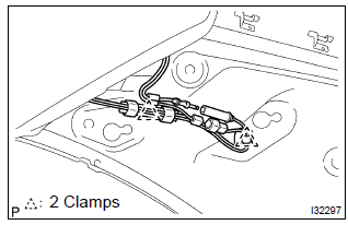
- Rear side: disconnect the connector and antenna cord plug.
- rear side: remove the 2 clamps.
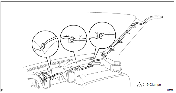
- Front side: remove the 9 clamps.
5. Remove roof headlining assy
Notice
: do not bend the roof headlining assy.
6. Remove antenna cord sub–assy
- remove the antenna cord sub–assy from the roof headlining.
7. Install antenna cord sub–assy
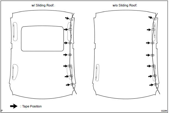
- tape the antenna cord sub–assy at the position of the roof headlining shown in the illustration.
Notice
:
- the antenna cord sub–assy should come to the center of the tape (100 mm(3.94 In.) X 25 mm(0.98 In.)) When taped.
- Try not to touch the adhesive side of the tape when taping.
- Install the roof headlining assy .
- engage the 9 clamps at the front side of antenna cord.
- connect the plug and connector at the rear side of antenna cord.
8. Install rear seat back assy (fixed type rear seat)
9. Install rear seat back assy (separated type rear seat)
10. Install bench type rear seat cushion assy( or 72–8)
11. Install instrument panel sub–assy upper
Hint
: refer to the procedure until the step, ”install instrument panel sub–assy upper” of instrument panel sub–assy lower.


Other materials:
Auto connection
To turn auto connection mode on, set “Bluetooth* Power” to on.
When you register a phone, auto connection will be activated. Always set it to
this mode and leave the Bluetooth® phone in a place where a connection can be established.
When the engine switch is turned to ACCESSORY or ON <IG ...
Driving tips
Winter driving tips
Carry out the necessary preparations and inspections before driving the vehicle
in winter. Always drive the vehicle in a manner appropriate to the prevailing weather
conditions.
Preparation for winter
● Use fluids that are appropriate to the prevailing outside temper ...
Ecm/pcm processor
Dtc p0606 ecm/pcm processor
Monitor description
The ecm continuously monitors its internal circuits. This self–check insures
that the ecm is functioning properly.
If a malfunction is detected, the ecm will set the appropriate dtc and
illuminate the mil.
The two cpus, main and sub cpu i ...