Toyota Corolla (E170) 2014–2019 Owners Manual / Instrument cluster / Warning lights and indicators
Toyota Corolla (E170): Warning lights and indicators
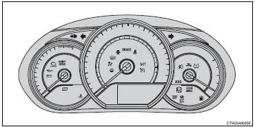
The warning lights and indicators on the instrument cluster and center panel inform the driver of the status of the vehicle’s various systems.
For the purpose of explanation, the following illustration displays all warning lights and indicators illuminated.
► Vehicles with a drive monitor display
► Vehicles with a multi-information display
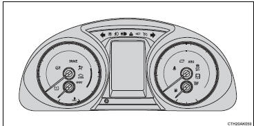
The units used on the meters and some indicators may differ depending on the target region.


Other materials:
Entire combination meter does not operate
Wiring diagram
Inspection procedere
1 Check fuse
Check that continuity exists of dome fuse.
check that continuity exists of gauge fuse.
check that continuity exists of am1 fuse.
2 Inspect combination meter assy
Check continuity.
Disconnect the ” ...
Automatic transaxle fluid (atm)
On–vehicle inspection
1. Check the fluid level
Hint:
drive the vehicle so that the engine and transaxle are at normal
operating temperature.
Fluid temperature: 70 – 80 °c (158 – 176 °f)
park the vehicle on a level surface and set the parking
brake.
with the engin ...
Editing the contact data
For PBAP compatible Bluetooth® phones, this function is available when “Automatic
Contact/History Transfer” is set to off. 1 Select “Edit Contact”.
2 Select the desired contact.
3 Select corresponding to the desired name or number.
► For editing the name
Follow the steps in “R ...