Toyota Corolla (E120) 2002–2008 Repair Manual / Starting & charging / Starting system
Toyota Corolla (E120): Starting system
Inspection
1. Inspect starter assy
Notice
: these tests must be performed within 3 to 5 seconds to prevent burnout of the coil.
- perform the pull–in test.
- Remove the nut, then disconnect the lead wire from terminal c.
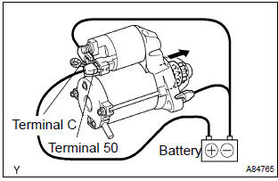
- Connect the battery to the starter repair service kit as shown in the illustration. Check that the clutch pinion gear is extended.
If the clutch pinion gear is not extended, replace the starter repair service kit.
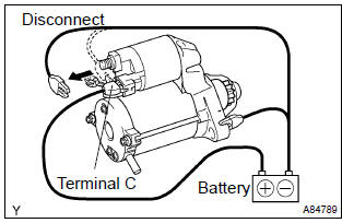
- Perform the hold–in test.
- Disconnect the negative (–) lead from terminal c
with the lead wire disconnected from terminal c.
Check that the clutch pinion gear remains extended.
If the clutch pinion gear returns, replace the starter repair service kit.
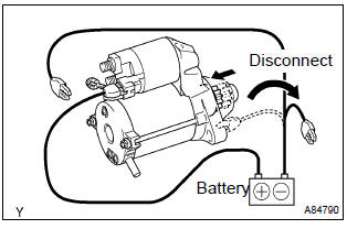
- Check the clutch pinion gear returns.
- Disconnect the negative (–) lead from the starter body. Check that the clutch pinion gear returns.
If the clutch pinion gear does not return, replace the starter repair service kit.
- Perform the no–load performance test.
- Connect the lead wire to terminal c with the nut.
Make sure that the lead is not grounded.
Torque: 10 nvm (102 Kgf·cm, 7 ft·lbf)
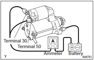
- Clamp the starter in a vise.
- Connect the battery and an ammeter to the starter as shown in the illustration.
- Check that the starter rotates smoothly and steadily
with the clutch pinion gear extended. Check that the
ammeter reads the specified current.
Specified current: 90 a or less at 11.5 V
If the current is not as specified, replace the starter repair service kit.
2. Inspect starter relay assy
- Check the continuity.
- Using an ohmmeter, check for continuity between each terminal.
Specified condition:
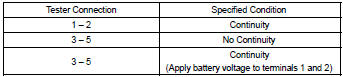
If the result is not as specified, replace the starter relay.


Other materials:
Circuit description
The d squib circuit consists of the airbag sensor assy center, spiral cable
sub–assy and horn button assy.
It causes the srs to deploy when the srs deployment conditions are satisfied.
Dtc b1180/17 is recorded when a short is detected in the d squib circuit (2nd
step).
Wiring diagra ...
Changing the passkey
1 Select “Passkey” using . 2 Input
a 4 to 8-digit passkey using .
Input the number 1 digit at a time.
3 When the entire number to be registered as a passkey has been input, press
again.
If the passkey to be registered has 8 digits, pressing
again is not necessary. ...
Driving support system
information display
■ Driving support system
information
Select to display the operational
status of the following systems:
Dynamic radar cruise control
LTA (Lane Tracing Assist)
LDA (Lane Departure Alert)
■ Navigation system-linked
display (if equipped)
Select to display the following
navigation system-linked ...