Toyota Corolla (E120): Replacement
1. Drain brake fluid
Notice
: wash the brake fluid off immediately if it comes into contact with any painted surface.
2. Remove front wheel rh
3. Remove front fender liner rh
4. Remove brake actuator with bracket
- turn the latch of the actuator connector to disconnect the connector.
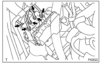
- Using sst, disconnect the 6 brake tubes from the brake
actuator.
Sst 09023–00100
- Attach tags or make a memo to identify the place to reconnect.
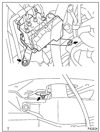
- Remove the nut, 2 bolts and brake actuator with bracket.
5. Remove brake actuator assy
- remove the 3 nuts and brake actuator from bracket.
6. Install brake actuator assy
- install the brake actuator with the 3 nuts to the bracket.
Torque: 4.7 Nvm (48 Kgf·cm, 42 in.Vlbf)
7. Install brake actuator with bracket
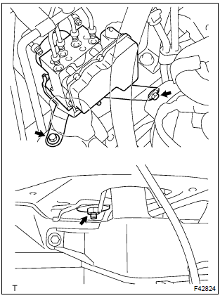
- Install the brake actuator with bracket with the nut and 2
bolts.
Torque: 19 nvm (194 Kgf·cm, 14 ft·lbf)
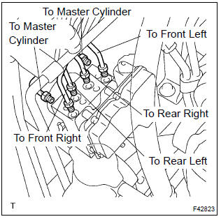
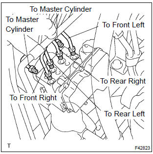
- Using sst, connect the 6 brake tubes to the correct position
of brake actuator, as shown in the illustration.
Sst 09023–00100
torque: 15.2 Nvm (155 Kgf·cm, 11 ft·lbf) - connect the brake actuator connector.
8. Install front fender liner rh
9. Install front wheel rh
torque: 103 nvm (1,050 Kgf·cm, 76 ft·lbf)
10. Fill reservoir with brake fluid
11. Bleed master cylinder
sst 09023–00100
12. Bleed brake line
13. Check fluid level in reservoir
14. Check brake fluid leakage
15. Check brake actuator with hand–held tester


Other materials:
Inspection procedure
1 Check p/t squib(lh) circuit(airbag sensor assy center – front seat
outer belt assy lh)
Disconnect the negative (–) terminal cable from the battery,
and wait at least for 90 seconds.
disconnect the connectors between the airbag sensor
assy center and the seat belt pretensio ...
Seat belt warning lamp for driver’s seat does not
operate
Wiring diagram
Inspection procedure
1 Check combination meter assy
Ground terminal c9–12 on the combination meter side.
check that the warning lightlights up.
Ok: warning light lights up.
2 Inspect front seat inner belt assy lh
Disconnect the front seat inner belt ...
Temporarily engaged gear steps selection mode in the D position
To drive in temporary gear steps selection mode, operate the “-” and “+” paddle
shift switches. The gear steps can then be selected by operating the “-” and “+”
paddle shift switches. By selecting gear step using paddle shift switches, you can
control engine braking forces.
1 ...