Toyota Corolla (E120): Pre–check
1. Diagnosis check
- Starting diagnosis mode (service check mode)
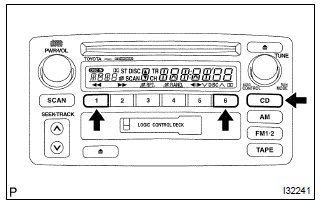
- turn off the audio system and turn the ig switch to acc. While pressing the preset switches ”1” and ”6” at the same time, press ”cd” 3 times.
- Reference:
- beep sound is given 3 times and the system enters the service check mode.
- It may take about 40 sec. To complete the check.
- In the service check mode, the system check
and the diagnosis memory check are performed,
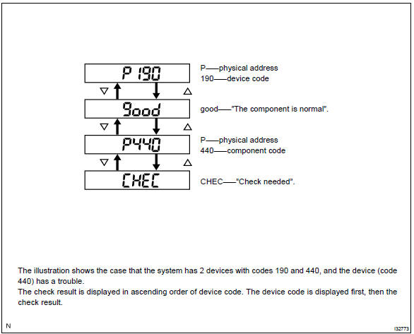
and the check results are displayed
in ascending order of the device codes.
(Physical address)
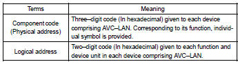
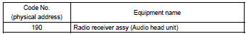
Code no. (Physical address) list
- Finishing diagnosis mode
- press ”cd” for 2 sec. Or more, or turn the ig switch off.
- Service check mode result display (for checking the current and the past system conditions)
- press the ”tune” switch to see the check result of each device.
- Check result display
|
Display |
Original language |
Meaning |
Action to be taken |
| Good | Good (normal) | No dtc is detected in both ”system check mode” and ”diagnosis memory mode”. |
– |
| Ncon | No connection | The system recognized the component when it was registered, but the component gives no response to the ”diagnosis mode on request”. | Check the power source circuit and the communication circuit of the device indicated by the device code (physical address). |
| Echn | Exchange | One or more dtc for ”exchange” is detected in either ”system check mode” or ”diagnosis memory mode”. | Go to the detail information mode to check the trouble area referring to the dtc list. |
| Chec | Check | When no dtc is detected for ”exchange”, one or more dtc for ”check is detected in either ”system check mode” or ”diagnosis memory mode”. | Go to the detail information mode to check the trouble area referring to the dtc list. |
| Old | Old version | Old dtc application is identified and dtc is detected in either ”system check mode” or ”diagnosis memory mode”. |
– |
| Nres | No response | The device gives no response to any one of ”system check mode on request”, ”system check result request” and ”diagnosis memory request”. | Check the power source circuit and the communication circuit of the device indicated by the device code (physical code). |
- To perform the service check again, press the preset switch ”1”.
- detail information mode (when displaying the troubled device’s dtc)
- with ”chec” or ”echn” being display, press the preset switch ”2” to go to the detail information mode.
- Press the ”tune” switch to display ”system check result (sys)” and ”diagnosis memory response (code)”.
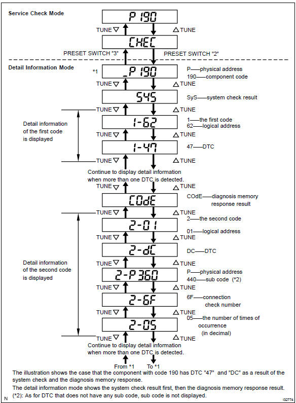
- Displayed items in detail information mode
|
Division code for dtc display |
Meaning |
Order of detailed information displayed when the ”tune up” switch is pressed. (The order is reversed when the ”tune down” switch is pressed.) |
| Sys | System check result is displayed. | Logical address dtc |
| Code | Diagnosis memory check result is displayed. | Logical address dtc sub code connection confirmation number the number of times of occurrence |
- Check the trouble area referring to the dtc list.
- to return to the service check mode, press the preset switch ”3”.
- clearing individual dtc memory (when clearing the memory of dtc detected in the pest individually)
- ) press the preset switch ”5” for 2 sec. Or more while the ”echn” is displayed in the service check mode or during the detail information mode.
Hint
:
- beep sound is given once when the dtc memory is completely cleared.
- When dtc memory is cleared, only the component code (physical address) is displayed for the target component.
- To check dtc, press the preset switch ”1” and perform the service check again.
- clearance of all dtc memory (when clearing all the memory of dtc detected in the past)
- start the diagnosis mode after repairing the trouble area.
- Press the preset switch ”5” for 2 sec. Or more. (”Clr” is displayed at this time.)
Hint
:
- beep sound is given once when the dtc memory is completely cleared.
- When dtc memory for all the device is cleared, only the component codes (physical address) are displayed.
- Press the preset switch ”1” to perform the service check again, and check that no dtc is displayed for all the component codes. (Physical address)
2. Identification of noise source
- Identify the condition under which the noise occurs, and check the noise filter on the related part.
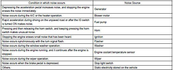
- Reference:
- make sure first that there is no noise from outside.
- Failing to do so makes the noise source detection difficult and leads to misunderstanding.
- The noise should be removed in descending order of loudness.
- Setting the radio untuned makes noise noticeable, making the recognition of the phenomenon easier.


Other materials:
Inspection procedure
Hand–held tester:
1 Check fuel tank cap assy(check that fuel tank cap is toyota
genuine parts)
2 Check that fuel tank cap is correctly installed
3 Inspect fuel tank cap assy
4 Check filler neck for damage
Remove the fuel tank cap.
visually check the fuel inlet pipe for ...
Precaution
1. Handling precautions on steering system
care must be taken when replacing parts. Incorrect replacement may
affect the performance of the
steering system and result in a driving hazard.
2. Handling precautions on srs airbag system
the vehicle is equipped with srs (suppl ...
Inspection procedure
1 Check door lock
When the door does not operate manually, proceed to ”a”.
when the door does not operate via the key, proceed to ”b”.
2 Inspect door lock control switch
W/ power window:
remove the power window regulator master switch assy.
Inspect th ...