Toyota Corolla (E120) 2002–2008 Repair Manual / Diagnostics / Audio system / Diagnostic trouble code chart
Toyota Corolla (E120): Diagnostic trouble code chart
|
Terms |
Terms |
| Physical address | Three–digit code (shown in hexadecimal) which is given to each
component comprising
the avc–lan.
Corresponding to the function, individual symbols are specified. |
| Logical address | Two–digit code (shown in hexadecimal) which is given to each function comprising the inner system of the avc–lan. |
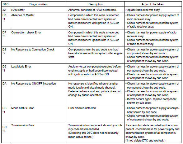
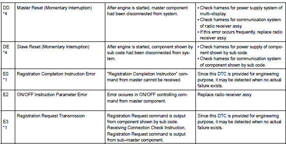
1. Radio receiver assy (physical address: 190)
Hint
: *1: even if no failure is detected, it may be stored depending on the battery condition or voltage for starting an engine.
*2: It is stored when 180 sec. Has passed after the power supply connector is pulled out after engine start.
*3: It may be stored when the engine key is turned 1 min. After engine start.
*4: It may be stored when the engine key is turned again after engine start.
*5: When 210 sec. Has passed after pulling out the power supply connector of the master component with the ignition switch in acc or on, this code is stored.
- Logical address: 01 (communication control)
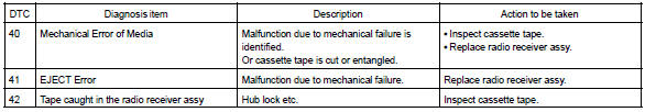
- Logical address: 61 (cassette switch)
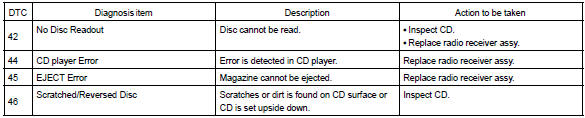
- Logical address: 62 (cd player)
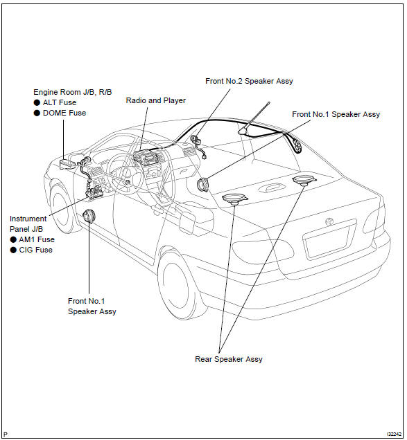
Location


Other materials:
Vehicle identification
■ Vehicle identification number
The vehicle identification number (VIN) is the legal identifier for your vehicle.
This is the primary identification number for your Toyota. It is used in registering
the ownership of your vehicle.
This number is stamped on the top left of the instrument p ...
Location
...
Inspection procedure
Hint:
if different dtcs related to different systems that have terminal e2
as the ground terminal are output
simultaneously, terminal e2 may be open.
Read freeze frame data using the hand-held tester or the obd ii scan
tool. Freeze frame data records
the engine conditions when a malf ...