Toyota Corolla (E120): Overhaul
Notice
: when installing, coat the parts indicated by the arrow with power steering fluid or molybdenum disulfide lithium base grease.
1. Precaution
2. Disconnect battery negative terminal
3. Inspect center front wheel
4. Remove horn button assy
5. Remove steering wheel assy
sst 09950–50013 (09951–05010, 09952–05010, 09953–05020, 09954–05021)
6. Remove front wheels
7. Remove engine under cover lh
8. Remove engine under cover rh
9. Disconnect tie rod end sub–assy lh
- Remove the cotter pin and nut.
- using sst, disconnect tie rod end sub–assy lh from the
steering knuckle.
Sst 09628–62011
10. Disconnect tie rod end sub–assy rh
sst 09628–62011
Hint
: remove the rh side by the same procedures as of the lh side.
11. Remove column hole cover silencer sheet
12. Disconnect steering intermediate shaft
13. Disconnect pressure feed tube assy
- Using sst, disconnect the pressure feed tube assy.
Sst 09023–38400
14. Disconnect return tube sub–assy
- Using sst, disconnect the return tube sub–assy.
Sst 09023–38400
- remove the bolt and disconnect the tube clamp.
15. Disconnect front stabilizer link assy lh
- remove the nut and disconnect the front stabilizer link assy lh.
16. Disconnect front stabilizer link assy rh
Hint
: remove the rh side by the same procedures as the lh side.
17. Disconnect front suspension arm sub–assy lower no.1 Lh
- Remove the bolt and 2 nuts and disconnect the front suspension arm sub–assy lower no.1 Lh from the lower ball joint.
18. Disconnect front suspension arm sub–assy lower no.1 Rh
Hint
: remove the rh side by the same procedures as the lh side. 19. Remove hood sub–assy
20. Remove cylinder head cover no.2
21. Suspend engine assembly
- Install the 2 engine hangers with the bolts in the correct
direction.
Parts no.:
No.1 Engine hanger: 12281 – 22021 no.2 Engine hanger: 12281 – 15040 bolt: 91512 – b1016
torque:
38 nvm (390 kgfvcm, 28 ftvlbf) - attach the engine chain hoist to the engine hangers.
Caution
: do not attempt to hang the engine by hooking the chain to any other parts.
22. Remove front suspension crossmember sub–assy
- Remove the 2 bolts and disconnect the center member from the engine mounting insulator fr.
- remove the 2 bolts and disconnect the center member from the frame.
- Remove the bolt and 3 nuts, disconnect the engine mounting insulator rr from the crossmember.
- using a transmission jack, support the crossmember.
- remove the 4 bolts and front suspension crossmember sub–assy with the steering gear assy.
23. Remove steering column hole cover sub–assy no.1
24. Remove steering intermediate shaft
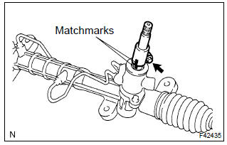
- Place matchmarks on the intermediate shaft with control valve.
- remove the bolt and steering intermediate shaft.
25. Remove rack & pinion power steering gear assy
- remove the 4 bolts and rack & pinion power steering gear assy from the crossmember.
26. Fix rack & pinion power steering gear assy
- Using sst, secure the rack & pinion power steering gear
assy in a vise.
Sst 09612–00012
27. Remove steering left turn pressure tube
- Using sst, remove the left turn pressure tube.
Sst 09023–38200
- remove the 2 o–rings from the left turn pressure tube.
28. Remove steering right turn pressure tube
- using sst, remove the right turn pressure tube.
Sst 09023–38200
- remove the 2 o–rings from the right turn pressure tube.
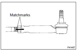
29. Remove tie rod end sub–assy lh
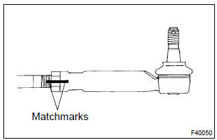
- Place matchmarks on the tie rod end with rack end.
- loosen the lock nut, and remove the tie rod end and lock nut.
30. Remove tie rod end sub–assy rh
Hint
: remove the rh side by the same procedures as the lh side.
31. Inspect tie rod end sub–assy lh
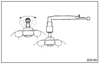
- Secure the tie rod end lh in a vise.
- install the nut to the stud bolt.
- flip the ball joint stud back and forth 5 times.
- using a torx wrench, turn the nut continuously at a rate of 2 – 4 seconds per 1 turn and take the torque reading of the 5th turn.
Turning torque: 0.49 – 3.43 Nvm (5.0 – 35 Kgfvcm, 4.34 – 30.38 In.Vlbf)
32. Inspect tie rod end sub–assy rh
Hint
: inspect the rh side by the same procedures as the lh side.
33. Remove steering rack boot no.1
- Remove the steering rack boot clip.
- using a screwdriver, remove the clamp and steering rack boot no.1.
34. Remove steering rack boot no.2
Hint
: remove the steering rack boot no.2 By same procedures as the no.1.
35. Remove steering rack end sub–assy
- Using a spanner, hold the steering rack steadily and using
sst, remove the rack end.
Sst 09922–10010
Notice
: use sst 09922–10010 in the direction shown in the illustration.
Hint
: mark the rh and lh rack ends.
- use the same manner described above to the other side.
36. Remove rack guide
- Using sst, remove the rack guide spring cap nut.
Sst 09922–10010 N
otice
: use sst 09922–10010 in the direction shown in the illustration.
- using a hexagon wrench (19 mm), remove the rack guide spring cap.
- remove the conical spring, rack guide spring and rack guide.
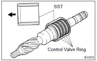
37. Remove power steering control valve
- remove the rack housing cap.
- Using sst, hold the control valve shaft and remove the
self–locking nut.
Sst 09616–00011
- Remove the 2 bolts and power steering control valve.
- remove the gasket.
- To prevent oil seal lip damage, wind vinyl tape around the serrated part of the control valve.
- using a plastic hammer, remove the control valve with oil seal from the control valve housing.
- remove the oil seal from the control valve.
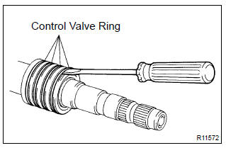
- Using a screwdriver, remove the 4 control valve rings.
Notice
: be careful not to damage the grooves for the control valve ring.
38. Remove power steering control valve upper oil seal
- Using sst and a press, remove the control valve upper
bearing and upper oil seal from the control valve housing.
Sst 09950–60010 (09951–00260), 09950–70010 (09951–07150)
39. Remove cylinder end stopper
- using snap ring pliers, remove the snap ring.
- pull out the cylinder end stopper.
40. Remove power steering rack
- using sst and a press, remove the steering rack with the
bushing.
Sst 09612–24014 (09612–10061) N
otice
: take care not to drop the steering rack.
- remove the o–ring from the bushing.
41. Remove power steering rack bush sub–assy
- Remove the power steering rack bush from the power steering rack.
- using sst, remove the rack bush oil seal.
Sst 09612–24014 (09613–22011)
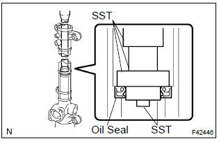
42. Remove power steering cylinder tube oil seal
- Using sst and a press, remove the power steering cylinder
tube oil seal.
Sst 09950–60010 (09951–00260), 09950–70010 (09951–07360)
43. Remove power steering control valve lower bearing
- Using sst and a press, remove the power steering control
valve lower bearing.
Sst 09950–70010 (09951–07100)
- Using sst and a press, remove the power steering control
valve center bearing.
Sst 09950–70010 (09951–07100)
44. Inspect power steering rack
- Using a screwdriver, remove the o–ring from the power steering rack bush sub–assy.
- using a dial indicator, check the steering rack for run out
and for teeth wear and damage.
Maximum run out: 0.1 Mm (0.004 In.)
- check the back surface for wear and damage.
45. Install power steering control valve lower bearing
- Coat a new bearing with molybdenum disulfide lithium base grease.
- using sst and a press, install the control valve center
bearing.
Sst 09950–60010 (09951–00220, 09951–00280, 09952–06010), 09950–70010 (09951–07100)
- Coat a new bearing with molybdenum disulfide lithium base grease.
- using sst and a press, install the control valve lower
bearing.
Sst 09950–60010 (09951–00280), 09950–70010 (09951–07100)
46. Install power steering cylinder tube oil seal
- Coat a new power steering cylinder tube oil seal lip with power steering fluid.
- using sst and a press, install the power steering cylinder
tube oil seal.
Sst 09950–60010 (09951–00240, 09951–00400, 09952–06010), 09950–70010 (09951–07360)
Notice
:
- make sure that the power steering cylinder tube oil seal is installed facing in the correct direction
- Take care so that the power steering cylinder tube oil seal will not be reversed when you install it.
47. Install power steering rack
- Coat a new power piston o–ring with power steering fluid and install it to the steering rack.
- coat a new power piston oil seal with power steering fluid.
- expand the power piston oil seal with your fingers.
Notice
: be careful not to expand the power piston oil seal excessively.
- Install the power piston oil seal to the steering rack, and
settle it down with your fingers.
Sst 09631–16020
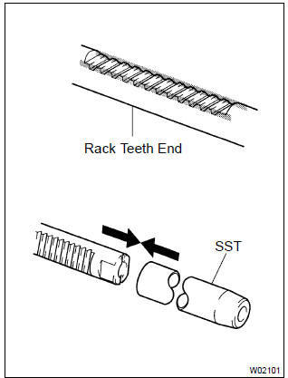
- Install sst to the steering rack.
Sst 09631–16020
H
int
: if necessary, scrape the burrs off the steering rack teeth end and burnish.
- coat the sst with power steering fluid.
- install the steering rack into the rack housing.
- remove the sst.
Sst 09631–16020
48. Install power steering rack bush sub–assy
- Using sst and a press, install the rack bush oil seal to the
power steering rack bush.
Sst 09950–60010 (09951–00400), 09950–70010 (09951–07100)
Notice
: make sure that the rack bush oil seal is installed facing in the correct direction.
- Coat a new o–ring with power steering fluid and install it to the power steering rack bush.
- To prevent rack bush oil seal lip damage, wind vinyl tape around the steering rack end, and apply power steering fluid.
- install the rack bush to the steering rack.
49. Install cylinder end stopper
- Using sst and a hammer, drive in the cylinder end stopper.
Sst 09612–22011
- using snap ring pliers, install a new snap ring to the rack housing.
50. Inspect rack & pinion power steering gear assy
- Install sst to the rack housing.
Sst 09631–12071 (09633–00010)
- apply vacuum of 53 kpa (400 mmhg, 15.75 In. Hg) for about 30 seconds.
- check that there is no change in the vacuum.
If there is a change in the vacuum, check the installation of the oil seals.
51. Install power steering control valve upper oil seal
- Coat an upper bearing and a new upper oil seal with power steering fluid.
- using sst and a press, install the upper oil seal.
Sst 09950–60010 (09951–00180, 09951–00320, 09952–06010), 09950–70010 (09951–07100)
Notice
: make sure that the oil seal is installed facing in the correct direction.
- Using sst and a press, install the upper bearing.
Sst 09950–60010 (09951–00190, 09951–00360, 09952–06010), 09950–70010 (09951–07100)
52. Install power steering control valve
- Expand 4 new control valve rings with your fingers.
Notice
: be careful not to over expand the valve ring.
- coat the 4 control valve rings with power steering fluid.
- install the 4 control valve rings to the control valve, and settle them down with your fingers.
- Carefully slide the tapered end of sst over the control
valve rings until they fit to the control valve.
Sst 09631–20081
Notice
: be careful not to damage the control valve rings.
- To prevent oil seal lip damage, wind vinyl tape around the serrated part of the control valve.
- install the control valve to the valve housing.
Notice
: be careful not to damage the control valve rings and oil seal lip.
- Coat a new oil seal lip with power steering fluid.
- using sst and a press, install the oil seal.
Sst 09612–22011
Notice
: make sure that the oil seal is installed facing in the correct direction.
- Apply grease to the needle bearing.
- install a new gasket to the valve housing.
- wind vinyl tape around the serration part of the control valve.
- install the valve housing to the rack housing with the 2
bolts.
Torque: 18 nvm (185 kgfvcm, 13 ftvlbf)
- Using sst, stop the control valve shaft rotation and install
a self–locking nut.
Sst 09616–00011
torque: 25 nvm (250 kgfvcm,18 ftvlbf) - apply sealant to 2 or 3 threads of the rack housing cap.
Sealant:
part no. 08833–00080, Three bond 1344, loctite 242 or equivalent - install the rack housing cap.
Torque: 59 nvm (600kgfvcm, 43 ftvlbf)
- Using a punch and a hummer, stake the rack housing cap and rack housing.
53. Install rack guide
- apply molybdenum disulfide lithium base grease to the contact surface of the power steering rack and of the rack guide.
- install the rack guide and compression spring to the rack housing.
- apply sealant to 2 or 3 threads of the rack guide spring cap.
Sealant:
part no. 0.8833–00080, Three bond 1344, loctite 242 or equivalent - temporarily install the rack guide spring cap.
54. Inspect total preload
- To prevent the steering rack teeth from damaging the oil seal lip, temporarily install the rh and lh rack ends.
- torque the rack guide spring cap.
Torque: 25 nvm (250 kgfvcm, 18 ftvlbf)
- back off the rack guide spring cap 12 .
- Using sst, turn the control valve shaft right and left 1 or
2 times.
Sst 09616–00011
- loosen the rack guide spring cap until the rack guide spring is not functioning.
- Using sst and torque wrench, tighten the rack guide
spring cap until the preload is within the specification.
Sst 09616–00011
preload (turning):
1.0 – 1.8 Nvm (20 – 18 kgfvcm, 8.6 – 15.7 Ftvlbf) - apply sealant to 2 or 3 threads of the rack guide spring
cap lock nut.
Sealant:
part no. 08833–00080, Three bond 1344, loctite 242 or equivalent - temporarily install the lock nut.
- Using a hexagon wrench (19 mm), hold the rack guide
spring cap and using sst, torque the nut.
Sst 09922–10010 torque: 43 nvm (440 kgfvcm, 32 ftvlbf)
Notice
: use sst 09922–10010 in the direction shown in the illustration.
Hint
: use a torque wrench with a fulcrum length of 345 mm (13.58 In.).
- recheck the total preload.
Preload (turning):
1.0 – 1.8 Nvm (10 – 18 kgfvcm, 8.6 – 15.7 Ftvlbf) - remove the rh and lh rack ends.
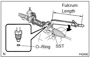
55. Install steering rack end sub–assy
- Using a spanner, hold the steering rack steadily and using
sst, install the 2 rack ends.
Sst 09922–10010
torque: 62 nvm (630 kgfvcm, 46 ftvlbf)
N
otice
: use sst 09922–10010 in the direction shown in the illustration.
Hint
:
- using sst, hold the rack and install the rack and sub– assy.
- Use a torque wrench with a fulcrum length of 380 mm (14.96 In.).
- Ensure that the steering rack hole is not clogged with grease.
Hint
: if the hole is clogged, the pressure inside the boot will change after it is assembled and steering wheel is turned.
56. Install steering rack boot no.2
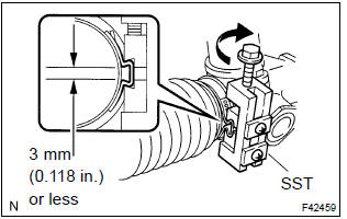
- Install the steering rack boot no.2.
- using sst, tighten the steering rack boot no.2 Clamp, as
shown in the illustration.
Sst 09521–24010
clearance: 3.0 Mm (0.118 In.) Or less
Notice
: be careful not to damage the boot.
- using a pliers, install the rack boot clip.
57. Install steering rack boot no.1
Hint
: install the rack boot no.1 By the same procedures as the rack boot no.2.
58. Install tie rod end sub–assy lh
- Screw the lock nut and tie rod end sub–assy lh onto the rack end until the matchmarks are aligned.
Hint
: after adjusting toe–in, torque the lock nut . Torque: 74 nvm (750 kgfvcm, 54 ftvlbf)
59. Install tie rod end sub–assy rh
Hint
: install the rh side by the same procedures as the lh side.
60. Install steering right turn pressure tube
- Coat 2 new o–rings with power steering fluid and install them to the right turn pressure tube.
- using sst, install the right turn pressure tube to the steering
gear assy.
Sst 09023–38200
torque:12 nvm (120 kgfvcm, 8 ftvlbf)
Hint
:
- use a torque wrench with a fulcrum length of 345 mm (13.58 In.).
- This torque value is effective in the case that sst is parallel to a torque wrench.
61. Install steering left turn pressure tube
- coat 2 new o–rings with power steering fluid and install them to the left turn pressure tube.
- using sst, install the left turn pressure tube to the steering
gear assy.
Sst 09023–38200
torque 12 nvm (120 kgfvcm, 8 ftvlbf)
Hint
:
- use a toque wrench with a fulcrum length of 345 mm (13.58 In.).
- This torque value is effective in the case that sst is parallel to a torque wrench.
62. Install rack & pinion power steering gear assy
- install the power steering gear assy with the 4 bolts and nuts.
Torque 58 nvm (590 kgfvcm, 43 ftvlbf)
Notice
:
- the 4 bush must be securely installed to the power steering gear assy.
- When tightening the installation bolt for power steering gear, the bush should not bitten in.
63. Install steering intermediate shaft
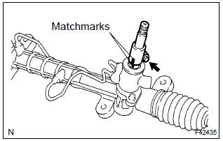
- Align the matchmarks on the steering intermediate shaft with steering pinion shaft.
- install the bolt.
Torque: 35 nvm (360 kgfvcm, 26 ftvlbf)
64. Install steering column hole cover sub–assy no.1
65. Install front suspension crossmember sub–assy
- Using sst, align the holes of the front suspension member
rh and body, and temporarily tighten the bolt in order
of a, b.
Sst 09670–00010
- Using sst, align the holes of the front suspension member
lh and body, and temporarily tighten the bolt in order
of a, b.
Sst 09670–00010
- using sst, align the holes of the front suspension member
rh and body, and torque the bolt a and b.
Sst 09670–00010
torque:
bolt a: 157 nvm (1,600 kgfvcm, 116 ftvlbf) bolt b: 157 nvm (1,600 kgfvcm, 116 ftvlbf) - using sst, align the holes of the front suspension member
lh and body, and torque the bolt a and b.
Sst 09670–00010
torque:
bolt a: 157 nvm (1,600 kgfvcm, 116 ftvlbf) bolt b: 157 nvm (1,600 kgfvcm, 116 ftvlbf)
- Connect the engine mounting insulator rr to the crossmember
with the bolt and 3 nuts.
Torque: 52 nvm (530 kgfvcm, 38 ftvlbf)
- Install the center member to the frame with the 2 bolts.
Torque: 39 nvm (400 kgfvcm, 29 ftvlbf)
- connect the engine mounting insulator fr to the center
member with the 2 bolts.
Torque: 52 nvm (530 kgfvcm, 38 ftvlbf)
66. Connect front suspension arm sub–assy lower no.1 Lh
- Connect the front suspension lower arm no.1 To the lower
ball joint with the bolt and 2 nuts.
Torque: 89 nvm (910 kgfvcm, 66 ftvlbf)
67. Connect front suspension arm sub–assy lower no.1 Rh
Hint
: use the same manner described above to the other side. 68. Connect front stabilizer link assy lh
- connect the front stabilizer link assy lh with the nut.
Torque: 74 nvm (755 kgfvcm, 55 ftvlbf)
69. Connect front stabilizer link assy rh
Hint
: use the same manner described above to the other side.
70. Connect return tube sub–assy
- Using sst, connect the return tube sub–assy.
Sst 09023–38400
torque: 23 nvm (235 kgfvcm, 17 ftvlbf)
Hint
:
- use a torque wrench with a fulcrum length of 345 mm (13.58 In.).
- This torque value is effective in case that sst is parallel to a torque wrench.
71. Connect pressure feed tube assy
- using sst, connect the pressure feed tube assy.
Sst 09023–38400
torque: 23 nvm (235 kgfvcm, 17 ftvlbf)
Hint
:
- use a torque wrench with a fulcrum length of 345 mm (13.58 In.).
- This torque value is effective in case that sst is parallel to a torque wrench.
- Connect the tube clamp with the bolt.
Torque: 7.8 Nvm (80 kgfvcm, 69 ftvlbf)
72. Connect steering intermediate shaft
73. Connect tie rod end sub–assy lh
- connect the tie rod end sub–assy lh with the nut.
Torque: 49 nvm (500 kgfvcm, 36 ftvlbf)
- install a new cotter pin.
Notice
: if the holes for a new cotter pin are not aligned, tighten the nut further up to 60 .
74. Connect tie rod end sub–assy rh
H
int
: use the same manner described above to the other side.
75. Install engine under cover lh
76. Install engine under cover rh
77. Install front wheels
torque: 103 nvm (1,050 kgfvcm, 76 ftvlbf)
78. Inspect center front wheel
79. Install column hole cover silencer sheet
- install the column hole cover silencer sheet with the 2 nuts.
80. Add power steering fluid
81. Bleed power steering fluid
82. Inspect fluid leak
83. Install cylinder head cover no.2
- install the cylinder head cover no.2 With 2 nuts and 2 clips.
Torque: 7.0 Nvm (71 kgfvcm, 62 ftvlbf)
84. Install hood sub–assy
85. Inspect hood sub–assy
86. Adjust hood sub–assy
87. Center spiral cable
88. Install steering wheel assy
89. Install horn button assy
90. Inspect and adjust front wheel alignment
91. Inspect srs warning light


Other materials:
Inspection procedure
Hint:
if different dtcs related to different systems that have terminal e2
as the ground terminal are output
simultaneously, terminal e2 may be open.
Read freeze frame data using the hand-held tester or the obd ii scan
tool. Freeze frame data records
the engine conditions when a malf ...
Interior
SRS airbags
Floor mats
Front seats
Head restraints
Seat belts
Console box
Inside lock buttons
Cup holders
Rear seats
Rear seat heater switches*
*: If equipped
■Ceiling
Inside rear view mirror
Sun visors
Vanity mirrors
Vanity lights*
Interior lights/personal lights
Moon roof sw ...
Radiator assy
Replacement
1. Drain coolant
2. Separate radiator hose inlet
3. Separate radiator hose outlet
4. Separate oil cooler inlet tube no.1
5. Separate oil cooler outlet tube no.1
6. Remove radiator assy
disconnect the fan motor connector.
disconnect two clamps for wire–harness fr ...